Turbine oil pipeline pure water cleaning system

A steam turbine oil and cleaning system technology, applied in the field of oil pipeline cleaning, can solve the problems of insignificant cleaning effect, secondary pollution, labor and time-consuming, etc., and achieve significant economic value and social benefits

Inactive Publication Date: 2011-12-21
ANHUI KANGDI ELECTRIC POWER SCI & TECH
View PDF4 Cites 8 Cited by
  • Summary
  • Abstract
  • Description
  • Claims
  • Application Information

AI Technical Summary

Problems solved by technology

However, the current methods and procedures such as chemical cleaning, oil flushing, and pipe dismantling cleaning are compl

Method used


Image

  • Turbine oil pipeline pure water cleaning system
  • Turbine oil pipeline pure water cleaning system

Examples


Embodiment Construction

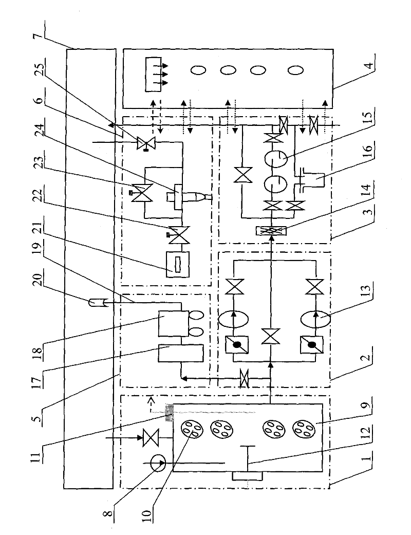
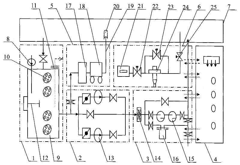
[0017] As shown in the drawings, the present invention consists of a pure water cleaning liquid preparation subsystem 1, a large flow cleaning subsystem 2, a quality purification subsystem 3, a cleaning regulation subsystem 4, a high-pressure cleaning subsystem 5 and a compressed air purging subsystem 6 constitute.

[0018] in:

[0019] The pure water cleaning solution preparation subsystem 1 includes: a self-priming pump 8 , a preparation box 9 , a combined heating tube 10 , a contact temperature sensor 11 , and a stirrer 12 .

[0020] The large-flow cleaning subsystem 2 includes: a dual-combination large-flow multi-suction cleaning pump station 13 .

[0021] The quality purification subsystem 3 includes: a strong magnetic filter 14 , a particle filter (two groups are shown in the figure) 15 , and a quality improvement processing filter 16 .

[0022] The cleaning control subsystem 4 includes: a temperature control subsystem, a pressure control subsystem, a flow control sub...


PUM


Abstract

The invention discloses a pure water cleaning system for steam turbine oil pipeline, comprising a pure water cleaning liquid preparation subsystem, a large flow cleaning subsystem, a quality purification subsystem, a cleaning control subsystem, a high pressure cleaning subsystem and a compressed air purge subsystem ; The pure water cleaning liquid preparation subsystem, the large flow cleaning subsystem, the quality purification subsystem are connected with the cleaning control subsystem, and the information collection, transmission and adjustment are carried out through the cleaning control subsystem; the high pressure cleaning subsystem and the large flow cleaning subsystem The connection and functions complement each other; the compressed air flushing subsystem is connected with the cleaning control subsystem. The invention realizes the patterned, programmed and intelligentized management of the pure water cleaning process, can efficiently, quickly, safely and thoroughly clean the steam turbine oil pipeline system, achieves the purpose of high cleaning and surface protection, and has significant economic value and social benefit.

Description

technical field [0001] The invention relates to the field of oil pipeline cleaning, in particular to a steam turbine oil pipeline cleaning system. Background technique [0002] The impurities existing in the steam turbine generator oil pipeline system of the power plant generally come from: 1. Impurities retained in the manufacturing and installation process, such as welding slag, rust, iron filings, paint skin, fibers, etc.; 2. When the system is running at a slight negative pressure Pollutants invaded from outside, such as dust and sediment; 3. Glue, carbon deposits, etc. produced by the long-term high temperature and high pressure operation of lubricating oil; 4. Impurities and garbage brought in by the system during maintenance or oil replenishment; 5. System coating exfoliation and corrosion products on metal surfaces, such as iron oxide and iron sulfide. [0003] The above impurities are intertwined to form sludge, oil pollution, etc., which adhere to the inner wall o...

Claims


Application Information

Patent Timeline
IPC IPC(8): B08B9/032
Inventor 赵东楼
Owner ANHUI KANGDI ELECTRIC POWER SCI & TECH
Why Eureka
Try Eureka