Wastewater treatment system and method

a technology of wastewater treatment system and wastewater treatment method, which is applied in the direction of feed/discharge of settling tanks, rigid containers, container/bottle construction, etc., can solve the problems of untreated wastewater discharge, environmental pollution, and the level of dissolved oxygen in the receiving water begins to deplete, so as to prevent inadvertent floatation

Active Publication Date: 2011-07-14
EARLY DANIEL M
View PDF35 Cites 48 Cited by
  • Summary
  • Abstract
  • Description
  • Claims
  • Application Information

AI Technical Summary

Benefits of technology

This patented technology allows two different chambers - one called the secondary compartment where mixed liquor can be separated into solid-liquid components (soluble) and liquid ones by means of gravity flow. After separation, clean treated water flows towards either side: this helps reduce pollution caused by excess organic matter present on surfaces being worked upon.

Problems solved by technology

The technical problem addressed in this patent text is the need for a wastewater treatment system that can protect the environment and promote public health, while also being cost-effective and flexible in adjustment to specific project requirements. Current centralized treatment plants have limitations in their capacity and can lead to untreated wastewater being released into the environment, causing pollution and harm to human health. Additionally, septic systems can also lead to environmental pollution and health concerns due to the buildup of solids. The use of large, pre-developed molds and inflexible tankage materials can also result in increased maintenance and operational expenses. A wastewater treatment system and method that can address these issues is needed.

Method used


Image

  • Wastewater treatment system and method
  • Wastewater treatment system and method
  • Wastewater treatment system and method

Examples


Embodiment Construction

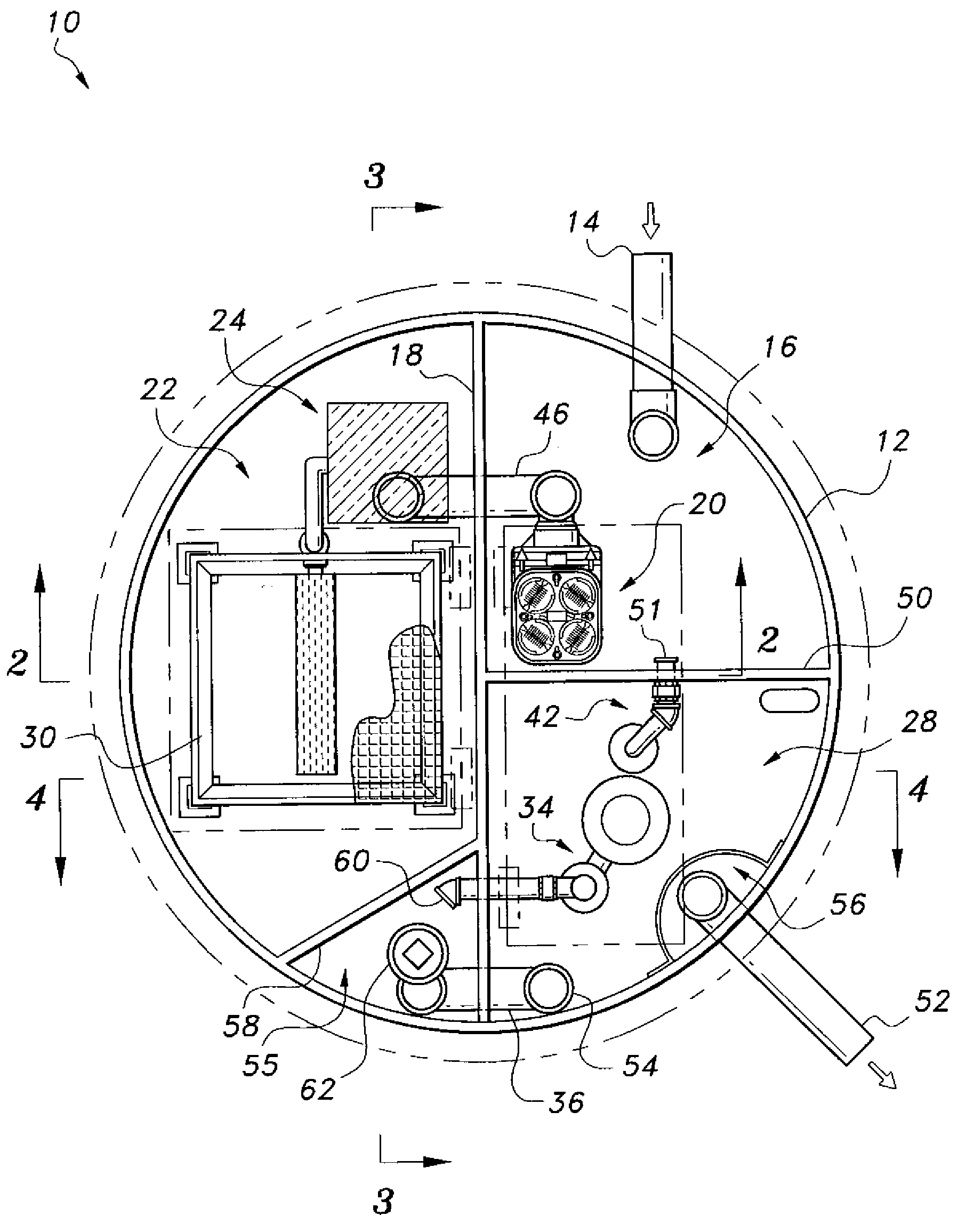
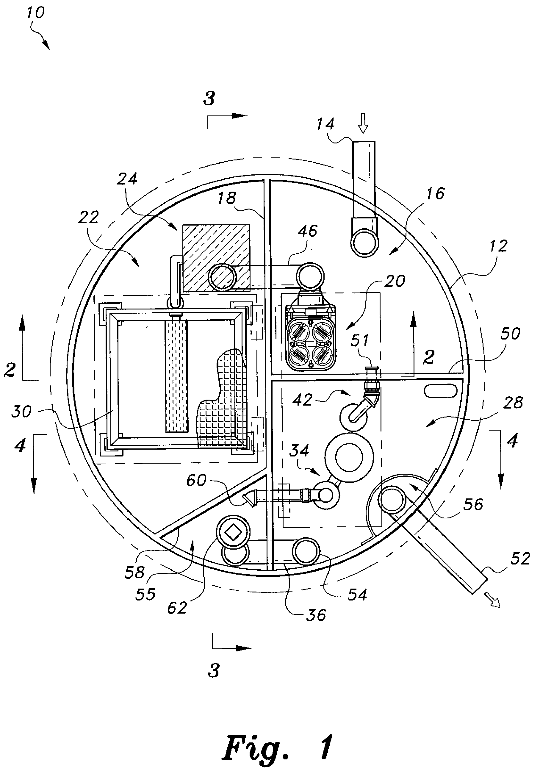
[0038]Referring to FIGS. 1-4, in a first embodiment, the wastewater treatment system 10 is preferably formed as a single enclosed unit contained within a housing 12. The housing 12 is substantially cylindrical, and is preferably formed from steel-reinforced plastic or the like. As will be described in detail below, the system 10 provides three separate techniques for decontaminating wastewater contained within the single system, thus optimizing the decontamination of the wastewater.

[0039]The wastewater treatment system 10 includes the housing 12 forming an outer tank, and first and second partition walls 18, 50, respectively, dividing the tank into first, second and third chambers 16, 22, 28, respectively. The first partition wall 18 generally bisects the cylindrical housing 12 diametrically, and the second partition wall 50 is orthogonal to. the first partition wall 18, extending radially and generally bisecting one of the two semicylindrical spaces formed by the first partition wa...


PUM

PropertyMeasurementUnit
Flow rateaaaaaaaaaa
Densityaaaaaaaaaa
Thermal propertiesaaaaaaaaaa

Abstract

The wastewater treatment system provides multiple techniques for decontaminating wastewater contained within a single system, thus optimizing the decontamination of the wastewater. In one embodiment, the wastewater treatment system includes a steel-reinforced plastic tank having first and second partition walls dividing the tank into first, second and third chambers. The first chamber includes at least one first effluent filter and further contains anaerobic bacteria for removal of organic waste material from the wastewater received therein. The first chamber is configured for at least partial removal of particulate and organic matter from the wastewater. The second chamber includes an air diffuser and further contains aerobic bacteria for further removal of organic waste material from the wastewater received therein. The third chamber includes a sludge pump assembly and at least one second effluent filter. Resultant purified water is selectively discharged from the third chamber through an outlet port.

Description


Claims


Application Information

Patent Timeline
Owner EARLY DANIEL M
Why Eureka
Try Eureka