
Aerofoils

a technology of aerosol and aerosol, applied in the field of aerosol and wings, can solve the problems of degradation of stall characteristics, and achieve the effects of preventing ice formation, reducing stall characteristics, and reducing stall characteristics

Active Publication Date: 2011-07-14
ISRAEL AEROSPACE IND
View PDF28 Cites 5 Cited by
  • Summary
  • Abstract
  • Description
  • Claims
  • Application Information

AI Technical Summary

Benefits of technology

This configuration effectively reduces or prevents contaminant accretion on the secondary element, maintaining high lift and aerodynamic performance even in adverse conditions, thereby ensuring the aircraft's stability and control.

Problems solved by technology

Positive flap deflections of the second element of these airfoils may produce a further enhancement of maximum lift, and an improvement in minimizing or avoiding accretion of contaminants, but this may be accompanied with some degradation of their stall characteristics.

Method used


Image

  • Aerofoils
  • Aerofoils
  • Aerofoils

Examples


first embodiment

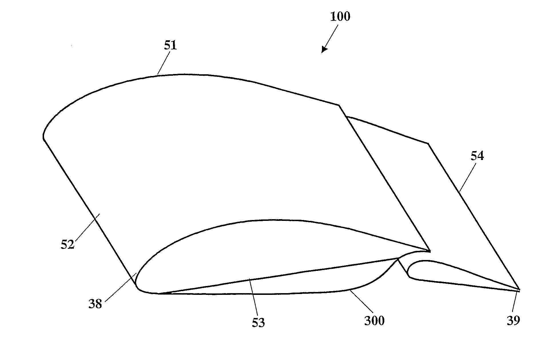
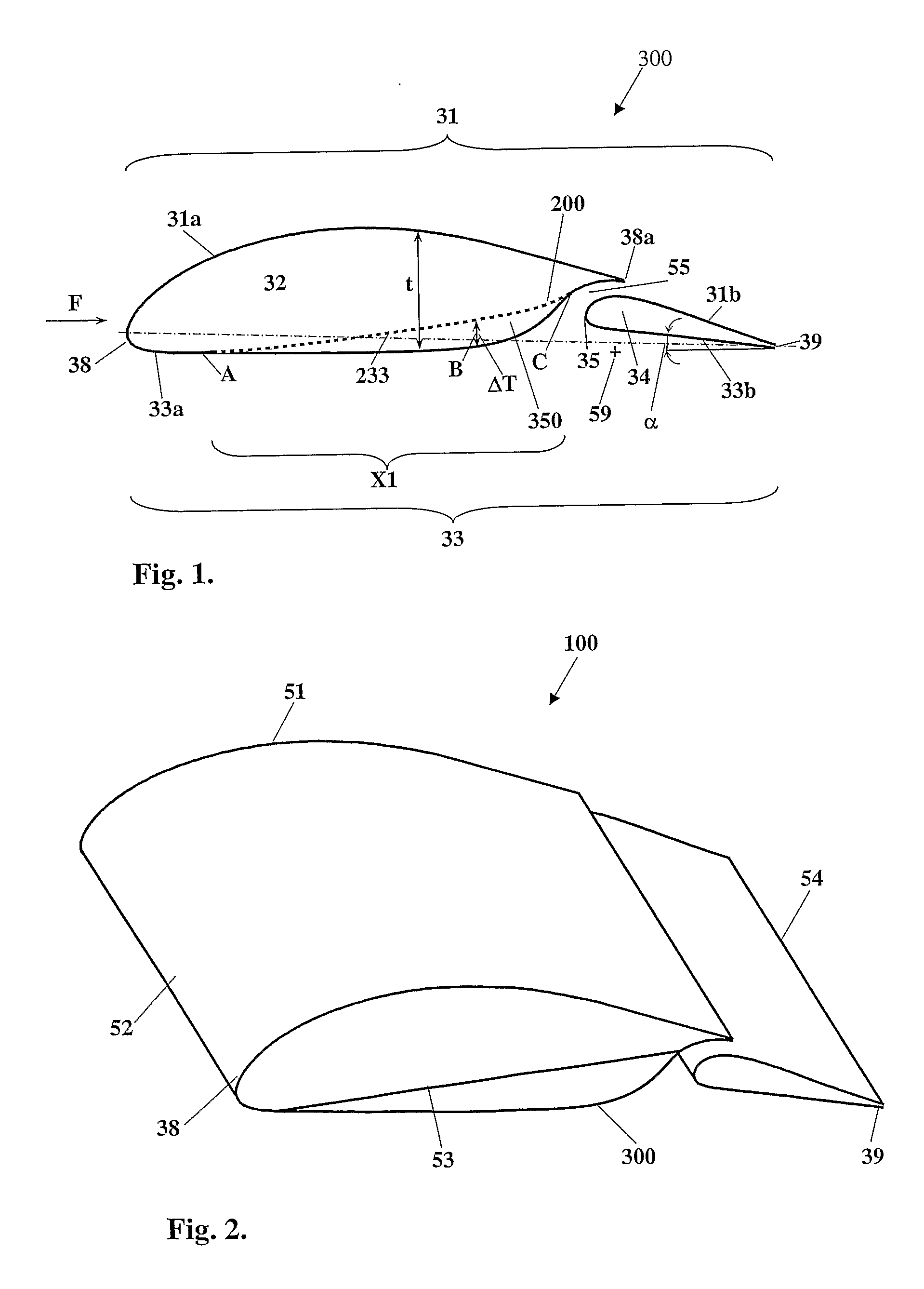
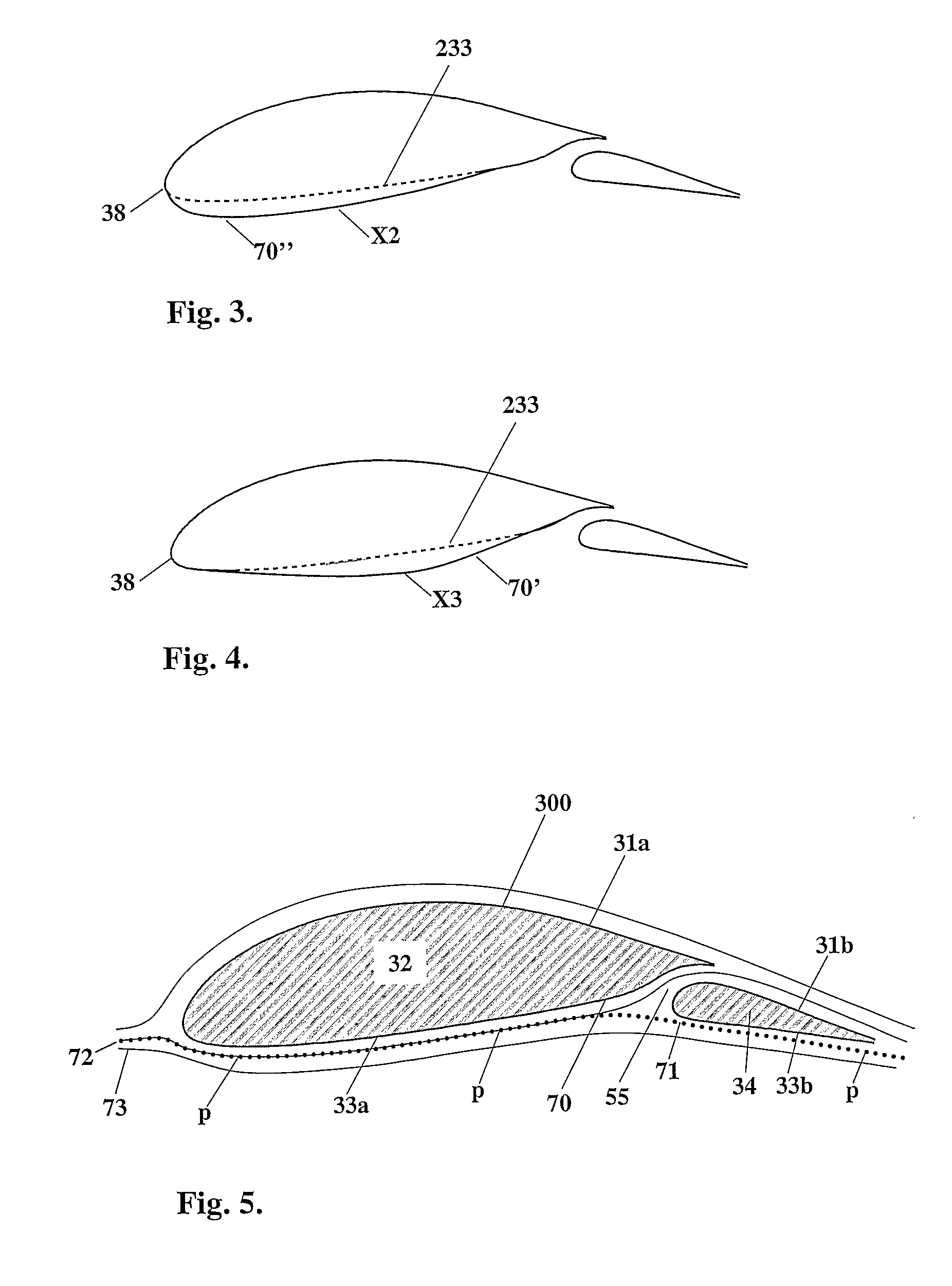
[0057]According to the invention, and referring to FIG. 1, a slotted aerofoil generally designated 300 may be based on a baseline aerofoil 200, or at least may be referenced to baseline aerofoil 200 for convenience, the baseline aerofoil 200 having substantially similar geometrical properties with respect to aerofoil 300. The main geometrical difference between the slotted aerofoil 300 and the baseline aerofoil 200 is that in the slotted aerofoil 300 the primary aerofoil element thereof has a profile configured for minimizing accretion of contaminant on the secondary aerofoil element, while the baseline aerofoil 200 is designed based on design rules that do not include specifically providing the primary aerofoil element thereof with a profile specifically configured for minimizing accretion of contaminant on the secondary aerofoil element. The baseline aerofoil 200 may be regarded as having a geometrically substantially identical suction surface and secondary element as for the aero...

second embodiment

[0094]In the second embodiment, the profile of pressure surface 433a also comprises an outwardly extending curvature, with respect to the corresponding profile of the baseline pressure surface profile 233, along a portion X4 of the pressure surface 433a, said portion X4 being intermediate between the leading edge 438 and a trailing end 438a of the primary aerofoil element 432, from a point A′ downstream of the leading edge 438, and returns to the baseline pressure surface profile 233 at point C′ proximate to the trailing end 438a. However, in this embodiment, the portion X4 comprises an upstream generally concave part X5 that smoothly dovetails into a downstream convex part X6 at point of inflexion B′. X5 thus resembles a curved surface that is generally facing towards a focal point or region thereof (away from the direction of the aerofoil), with the rate of change of slope of the contour of X5 generally increasing up to point B′. The generally concave portion X5 is configured for ...


PUM


Abstract

A two element aerofoil, and wing element based thereon, is provided, including a primary aerofoil element including a leading edge of the aerofoil and a secondary aerofoil element including a trailing edge of the aerofoil. A gap is provided between the primary aerofoil element and the secondary aerofoil element. The primary aerofoil element has at least one of a profile, orientation and location with respect to a respective at least one of a profile, orientation and location of the secondary aerofoil element that is configured for minimizing or avoiding accretion of contaminant on the secondary aerofoil element when subjected to an airflow that includes the contaminant, at least at one design set of conditions. A method for designing a two element aerofoil is also provided.

Description

FIELD OF THE INVENTION[0001]This invention relates to aerofoils and wings based on aerofoils, and in particular to methods and devices for reducing or preventing contamination of the same.BACKGROUND OF THE INVENTION[0002]Contaminants, for example ice, rain, water droplets, sand, smoke particles, dust particles, or other contaminants that may accumulate on external surfaces of aircraft, particularly aerofoils and other aerodynamic surfaces, can seriously affect the aerodynamic performance, in particular the lift and drag characteristics, of the aircraft, and can also change the weight and centre of gravity of the aircraft.[0003]For laminar wings, relatively minor wing contamination or flow disturbances (depending on Reynolds number) can produce a complete loss of laminar flow on the wing surfaces, and the loss of laminar flow results in drag penalties and to deterioration of maximum lift. However, strong contamination with the ensuing more significant flow disturbances, may go beyond...

Claims


Application Information

Patent Timeline
Patent Type & Authority Applications(United States)
IPC IPC(8): B64D15/18B64C3/14B64C9/16G06F17/50
CPCB64C3/14B64C3/44B64C3/48Y02T50/145B64C2003/148Y02T50/12B64C2003/142Y02T50/10
Inventor SHEPSHELOVICH, MICHAELABRAMOV, DANNY
Owner ISRAEL AEROSPACE IND
Learn More