Aerofoil accessories and method for modifying the geometry of a wing element

a technology of aerofoil and accessories, applied in the field of aerofoil accessories and the geometry of wing elements, can solve problems such as the degradation of stall characteristics of aircraft, and achieve the effects of mild stall performance, high lift and high li

Active Publication Date: 2011-07-07
ISRAEL AEROSPACE IND
View PDF34 Cites 11 Cited by
  • Summary
  • Abstract
  • Description
  • Claims
  • Application Information

AI Technical Summary

Benefits of technology

[0039]The first accessory is configured for being attached to a suction surface of said wing element and configured for effectively providing said modified profile with at least a change in a suction surface profile thereof with respect to said datum profile. The first accessory may be configured for providing said wing element with high lift, mild stall performance relative to said wing element absent said accessory. The first accessory may comprise an outwardly facing accessory surface having a local curvature that may increase, and/or that may remain substantially constant, along the chord in a direction towards a trailing edge of the primary element when said accessory is attached to the wing element.
[0040]The said second accessory may comprise an outwardly facing surface having an accessory profile configured for minimizing or preventing flow into said gap of said contaminants that may be flowing along or proximate to a boundary layer over said pressure surface. The accessory profile may be further configured to enable airflow through said gap for enabling aerodynamic operation of said two element aerofoil, and further configured such that the airflow through said gap is generally consistent with providing high lift aerodynamic characteristics to said aerofoil. The second accessory, when attached to the aerofoil, may provide a modified aerofoil profile configured to ensure that at least some streamlines proximate to the modified pressure surface of said primary aerofoil element follow a path including over a suction surface of said secondary aerofoil element via said gap, while concurrently providing a trajectory to contaminants flowing proximate to the modified pressure surface of said primary aerofoil element such as to cause said contaminants to overshoot said gap. The accessory surface profile may extend outwardly along at least a portion of the chord of said primary aerofoil element with respect to the original pressure surface profile of the aerofoil. The accessory surface p...

Problems solved by technology

Positive flap deflections of the second element of these airfoils may produce a further enhancement of maximum lift, and an improvem...

Method used


Image

  • Aerofoil accessories and method for modifying the geometry of a wing element
  • Aerofoil accessories and method for modifying the geometry of a wing element
  • Aerofoil accessories and method for modifying the geometry of a wing element

Examples


first embodiment

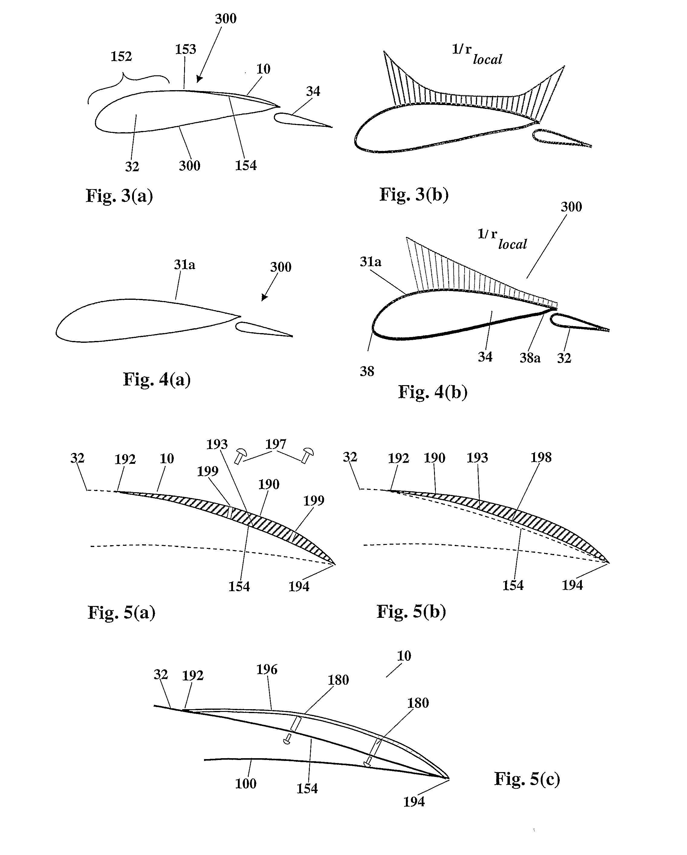
[0061]According to the invention, and referring to FIG. 1, an aerofoil accessory generally designated 10, is provided for two-element high lift, permanently slotted wings of an aircraft, in particular fixed wing aircraft. According to this embodiment, the accessory 10 is in the form of a “mild stall ramp” or “MS ramp”, that is configured for modifying the geometric profile of a datum two element slotted aerofoil section when attached thereto to provide mild stall characteristics to the datum two-element slotted aerofoil. Mild stall slotted aerofoils integrally incorporating an MS ramp design are disclosed in copending application US2007 / 0278354 assigned to the present assignee, the contents of which are incorporated in full herein.

[0062]For the purpose of example, such an aircraft is described herein as a fixed-wing aircraft, comprising a regular subsonic / transonic configuration, having a fuselage section, main wings, empennage (e.g., tailplane, vertical stabilizer), and a propulsio...

second embodiment

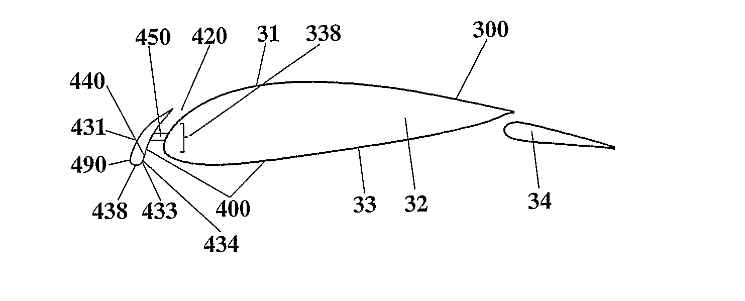
[0083]According to the invention, and referring to FIG. 7, an accessory is provided for modifying the effective leading edge profile and chord of datum aerofoil 300, by way of example, though the accessory may be provided for any other two-element aerofoil in a similar manner, mutatis mutandis. The accessory 410 according to this embodiment modifies the datum aerofoil profile 300 in a manner such as to provide a slot 420 close to the leading edge 438 of the modified aerofoil profile 400. Clearly, in variations of this embodiment, the leading edge accessory may be applied also to single-element aerofoils as well, mutatis mutandis.

[0084]Accordingly, the accessory 410 provides an external surface 490 that effectively replaces a leading edge portion 338 of the datum aerofoil profile 300, including the leading edge 38, an upstream portion of the pressure surface 33, and an upstream portion of the suction surface 31 of the datum aerofoil 300. The accessory 410 thus provides a new leading...

third embodiment

[0090]According to the invention, and referring to FIGS. 9(a) to 9(c), an accessory is provided for modifying at least part of the pressure surface profile of datum aerofoil 300, by way of example, though the accessory may be provided for any other two-element aerofoil in a similar manner, mutatis mutandis. Accessory 510 according to this embodiment modifies the datum aerofoil profile 300 in a manner such as to outwardly project at least a portion of the pressure surface 533 of the datum aerofoil 300. Accordingly, the accessory 510 provides an external surface 590 that effectively replaces at least a portion of the pressure surface 533, of the datum aerofoil 300. In this embodiment, this portion is a downstream portion of the pressure surface 533 (FIG. 9(c)), though in various alternative variations of this embodiment, this portion may be substantially the full pressure surface 533 (FIG. 9(a)), an upstream portion thereof (FIG. 9(b)) or indeed any intermediate portion or portions of...


PUM


Abstract

Aerofoil accessories are provided, configured for selective attachment to a wing element, the wing element having an outer facing aerofoil surface and being based on at least one datum aerofoil section. Each accessory provides a modified geometric profile to a datum profile of the at least one aerofoil section when attached to the wing element. The accessories are each configured for having a substantially fixed geometric profile with respect to the at least one datum aerofoil section at least whenever said wing element is airborne with the respective accessory attached to the wing element. The modified geometric profile is such as to provide said wing element with the accessory attached thereto with a desired change in performance relative to a datum performance provided by the wing element absent the accessory. A kit is also provided for enhancing performance of a wing element in off-design conditions. A method is also provided for enhancing performance of a wing element in adverse conditions.

Description

FIELD OF THE INVENTION[0001]This invention relates to aircraft, wings and aerofoils, and in particular to accessories therefore.BACKGROUND OF THE INVENTION[0002]Geometric profiles of aerofoils, including wings, propeller blades, rotor / turbine blades, stabilizers, and so on, are in general optimized for a design set of conditions or a mission profile, for example high lift, endurance, low drag and so on. Nevertheless, devices such as leading edge slats and / or trailing edge flaps, permit the geometry of the aerofoil to be varied to a limited degree while airborne, and thus enable operation of the aerofoil at other conditions.[0003]However, aircraft that need at times to operate under a wide range of different conditions may incorporate aerofoil geometries that provide adequate performance for the range of conditions, albeit at a performance loss as compared with the optimum performance that may be obtained at any specific set of conditions with an aerofoil geometry designed for such a...

Claims


Application Information

Patent Timeline
IPC IPC(8): B64C3/44
CPCB64C3/14B64C3/44B64C3/48Y02T50/145B64C2003/148Y02T50/12B64C2003/142Y02T50/10
Inventor SHEPSHELOVICH, MICHAELNAGEL, ALEXABRAMOV, DANNY
Owner ISRAEL AEROSPACE IND
Why Eureka
Try Eureka