
Platform with automatic lubrication mechanism

Inactive Publication Date: 2011-07-14
HIWIN MIKROSYST
View PDF14 Cites 6 Cited by
  • Summary
  • Abstract
  • Description
  • Claims
  • Application Information

AI Technical Summary

Benefits of technology

[0007]It is therefore a primary object of the present invention to provide a platform with automatic lubrication mechanism, which can provide lubrication effect without using any additional power source so as to save energy.
[0008]It is a further object of the present invention to provide the above platform with automatic lubrication mechanism, which can be adaptively used in a vacuumed operation environment such as a vacuumed chamber to achieve reliable lubrication effect.
[0009]It is still a further object of the present invention to provide the above platform with automatic lubrication mechanism in which one single lubricating section can provide lubrication effect for more than one slide sections. Therefore, the load is reduced to save energy.

Problems solved by technology

However, considerably great frictional force still exists between the ball bodies and the faces in contact with the ball bodies.
However, in a vacuum operation environment, the lubricating oil will have very high viscosity so that the capillary effect will be unapparent.
However, most of the production equipments for the current high-precision semiconductor products or plane displays require vacuum environment.
However, in the vacuum environment, there is no medium so that the heat generated by the pressurizing pump 8 cannot be dissipated via air.
Moreover, the pressurizing pump 8 is an additional component with respect to the linear motor, which will occupy much room and lead to increment of load.
Accordingly, the pump-pressurized lubricating mechanism is not an optimal lubricating measure for the linear motor.

Method used


Image

  • Platform with automatic lubrication mechanism
  • Platform with automatic lubrication mechanism
  • Platform with automatic lubrication mechanism

Examples


Embodiment Construction

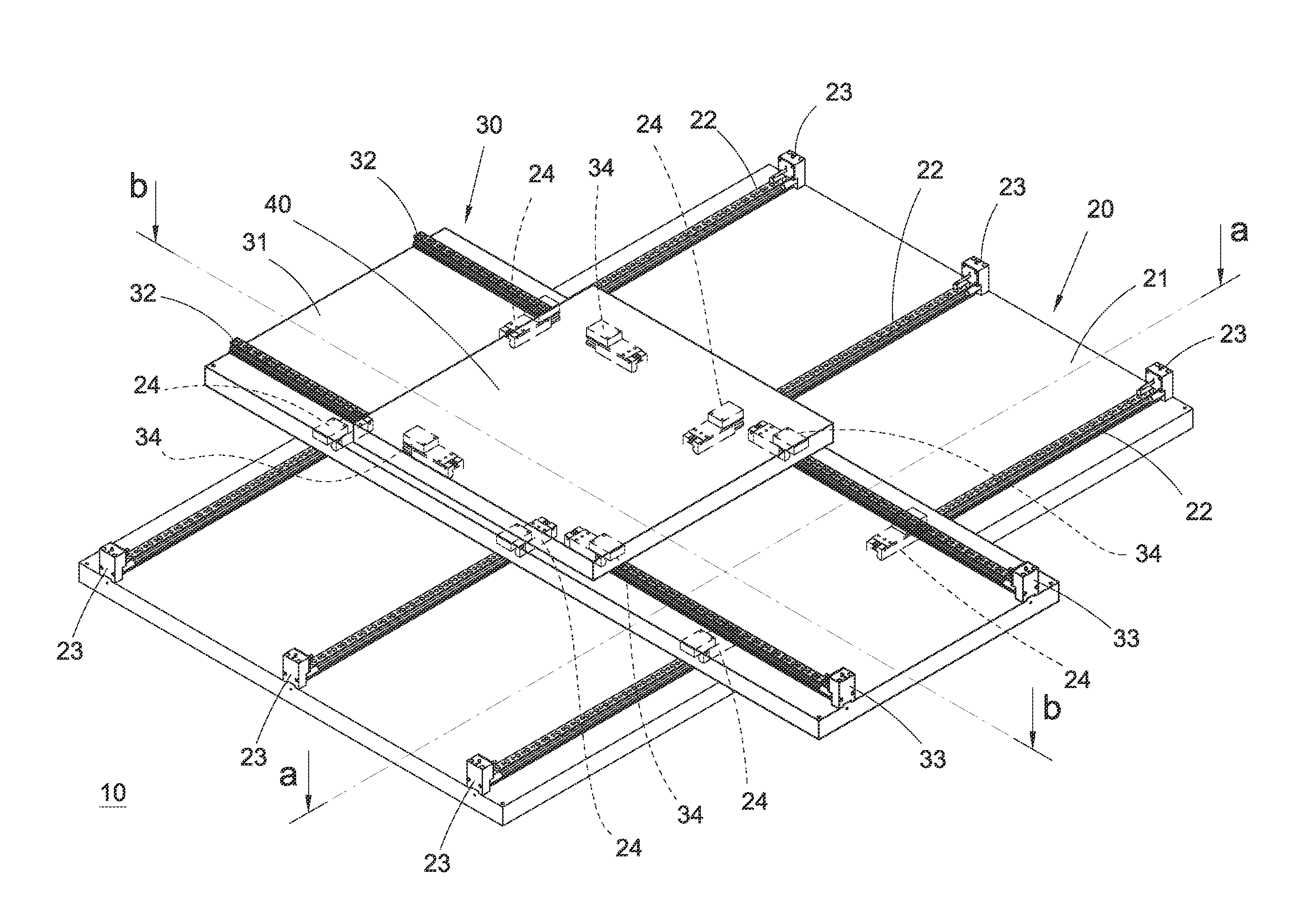
[0020]Please refer to FIGS. 4 to 7. According to a preferred embodiment, the platform 10 with automatic lubrication mechanism of the present invention includes a first platform assembly 20 and a second platform assembly 30. The first platform assembly 20 includes a rectangular board-like first platform section 21 with a certain thickness. The first platform section 21 is horizontally positioned as a base for a linear motor. Other components of the linear motor are arranged on the first platform section 21.

[0021]The first platform assembly 20 further includes three elongated first guide sections 22. The first guide sections 22 are fixedly disposed on an upper face of the first platform section 21 in parallel to the length of the rectangular first platform section 21.

[0022]The first platform assembly 20 further includes six first lubricating sections 23 without active power. The first lubricating sections 23 are fixedly disposed on the upper face of the first platform section 21 in ad...


PUM


Abstract

A platform with automatic lubrication mechanism. The platform includes at least one platform assembly. The platform assembly has at least two guide sections, at least two slide sections respectively slidably disposed on the guide sections, and at least two lubricating sections fixedly disposed on the guide sections. Each lubricating section has an internal cavity for containing therein a lubricant or the like, and an oil-filling passage extending from the cavity to the guide section to communicate with openings formed on one side of the guide section. Through the oil-filling passage, the cavity communicates with an exterior of the guide section. The slide section is movable to push a push member for making the lubricant or the like contained in the cavity spill out of the openings to provide lubrication effect between the guide section and the slide section.

Description

BACKGROUND OF THE INVENTION[0001]The present invention relates generally to a linear motor, and more particularly to a platform with automatic lubrication mechanism.[0002]FIG. 1 shows a conventional linear motor 1 having a mover 2 and a stator 3. The mover 2 is linearly reciprocally movable by means of the magnetic field effect between the mover 2 and the stator 3. The mover 2 is guided with linear guide rails 4 for controlling the linear track of the mover 2 and stabilizing the motion of the mover 2. The mover 2 is carried by sliders 5 slidably mounted on the slide rails 4, whereby the guide rails 4 can guide the mover 2 to reciprocally move.[0003]To speak more specifically, ball bodies or rollers are held between the sliders 5 and the slide rails 4 to reduce frictional force so as to stabilize and smoothen the relative sliding motion of the sliders 5 along the slide rails 4. However, considerably great frictional force still exists between the ball bodies and the faces in contact ...

Claims


Application Information

Patent Timeline
IPC IPC(8): F16C33/10
CPCF16C29/008F16C33/6659F16C29/0633
Inventor CHEN, TUNG-HSIN
Owner HIWIN MIKROSYST
Features
  • Generate Ideas
  • Intellectual Property
  • Life Sciences
  • Materials
  • Tech Scout
  • Unparalleled Data Quality
  • Higher Quality Content
  • 60% Fewer Hallucinations
Learn More