
Fluid Regulator Having Pressure Registration Flow Modifier

a technology of flow modifier and regulator, which is applied in the direction of fluid pressure control, process and machine control, instruments, etc., can solve the problems of limiting the overall capacity, limiting the accuracy class, and unreasonable expectation of pressure zone to be stationary in the pip

Active Publication Date: 2011-07-21
EMERSON PROCESS MANAGEMENT REGULATOR TECH INC
View PDF15 Cites 16 Cited by
  • Summary
  • Abstract
  • Description
  • Claims
  • Application Information

AI Technical Summary

Benefits of technology

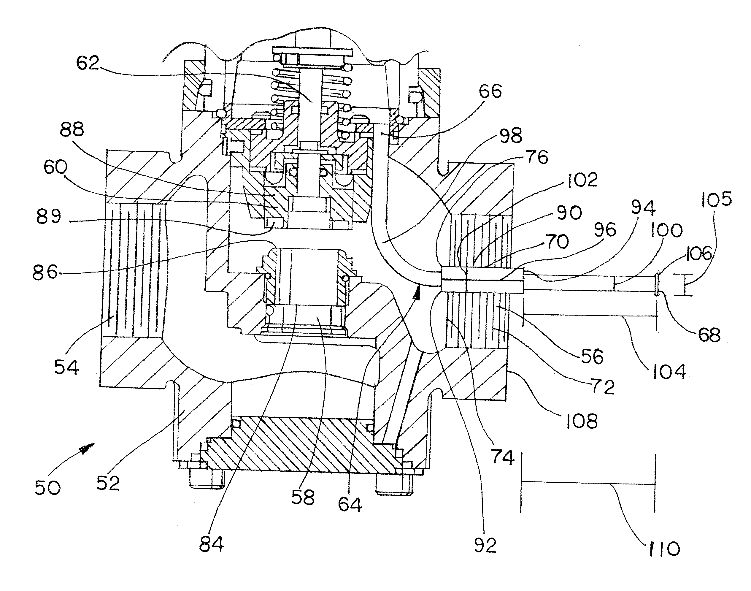
In accordance with another aspect of the invention, a fluid regulating device includes a valve body having an inlet, an outlet, and a valve port, the valve body defining a flow path extending from adjacent the inlet, through the valve port, and exiting through the outlet along an outlet axis. A control element is shiftably disposed within the valve body, the control element displaceable relative to the valve port to control the flow of a fluid between the inlet and the outlet. A control assembly comprises a valve actuator, the control assembly operatively coupled to the control element, the control assembly including a diaphragm disposed adjacent a diaphragm chamber. A sense tube having a first end, a second end, and an intermediate portion is provided, the first end positioned to provide flow communication with the diaphragm chamber of the control assembly, the second end disposed adjacent a distal portion of the outlet and the intermediate portion disposed adjacent an intermediate portion of the outlet. A flow interrupter is disposed in the flow path adjacent the intermediate portion of the sense tube, and a flared portion is disposed in the flow path adjacent the second end and downstream of the flow interrupter.
In accordance with yet another aspect, a method of sensing output pressure in a fluid regulating device, and / or a method of modifying an existing fluid regulating device, may comprise the steps of providing a valve body having an inlet, an outlet, and a valve port, the valve body defining a flow path extending from adjacent the inlet, through the valve port, and exiting through the outlet along an outlet axis, providing a control element shiftably disposed within the valve body, the control element displaceable relative to the valve port to control the flow of a fluid between the inlet and the outlet, and providing a control assembly comprising a valve actuator, with the control assembly operatively coupled to the control element, and with the control assembly including a diaphragm disposed adjacent a diaphragm chamber. A sense tube is provided and includes a first end, a second end, and an intermediate portion, and the sense tube is positioned with the first end in flow communication with the diaphragm chamber of the control assembly, and with the second end positioned adjacent a distal portion of the outlet of the valve body. A flow interrupter is positioned along the flow path adjacent an intermediate portion of the sense tube, and a flared portion is provided on the sense tube and positioned adjacent the second end of the sense tube and downstream of the flow interrupter.

Problems solved by technology

In real world applications however, it is unreasonable to expect the pressure zone to be stationary in the pipe as the flow path changes.
This sensed pressure fluctuation creates areas of increased boost and droop, which may limit overall capacity.
These pressure spikes may cause the outlet pressure to exceed the required accuracy class.

Method used


Image

  • Fluid Regulator Having Pressure Registration Flow Modifier
  • Fluid Regulator Having Pressure Registration Flow Modifier
  • Fluid Regulator Having Pressure Registration Flow Modifier

Examples


Embodiment Construction

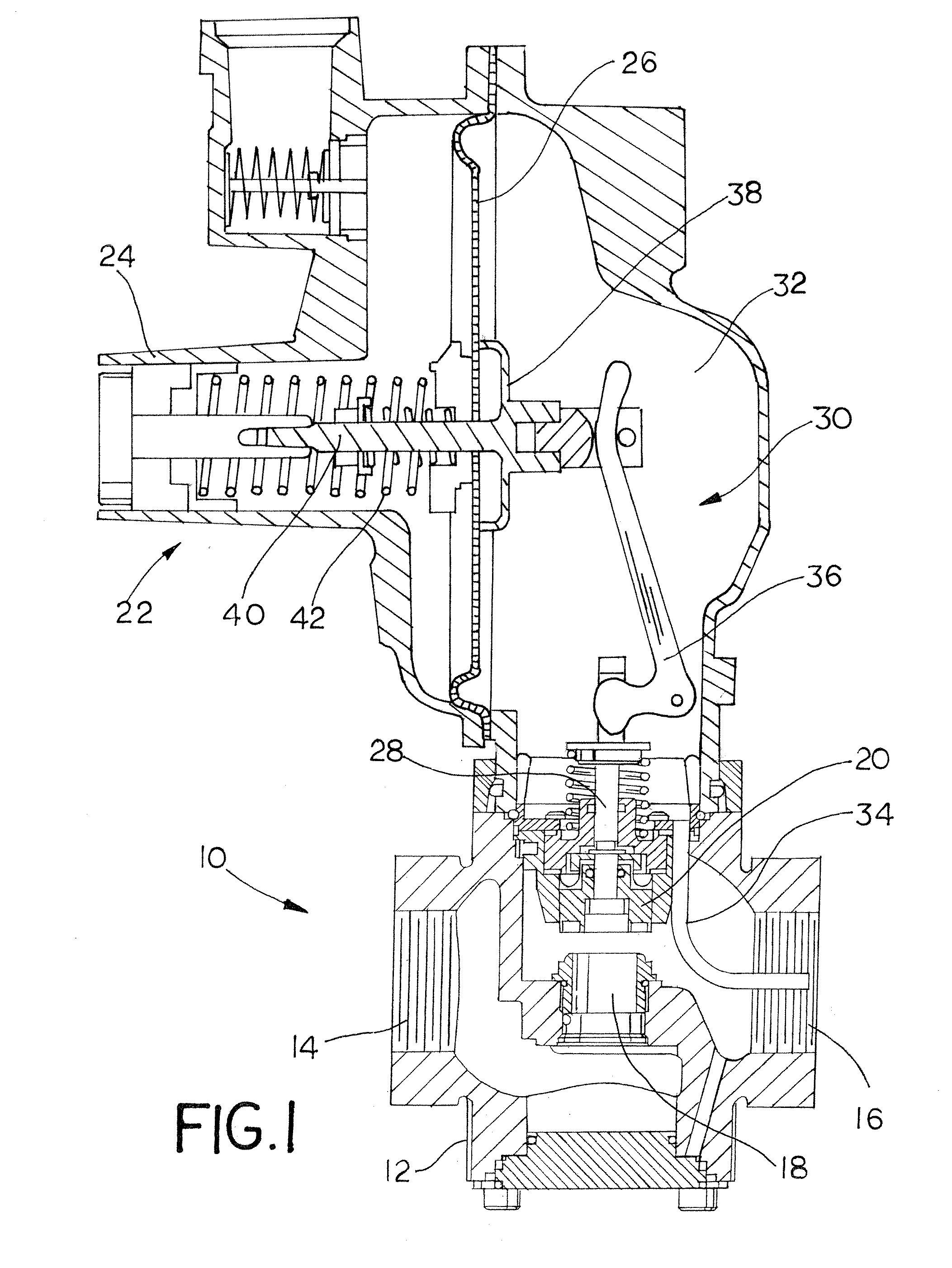
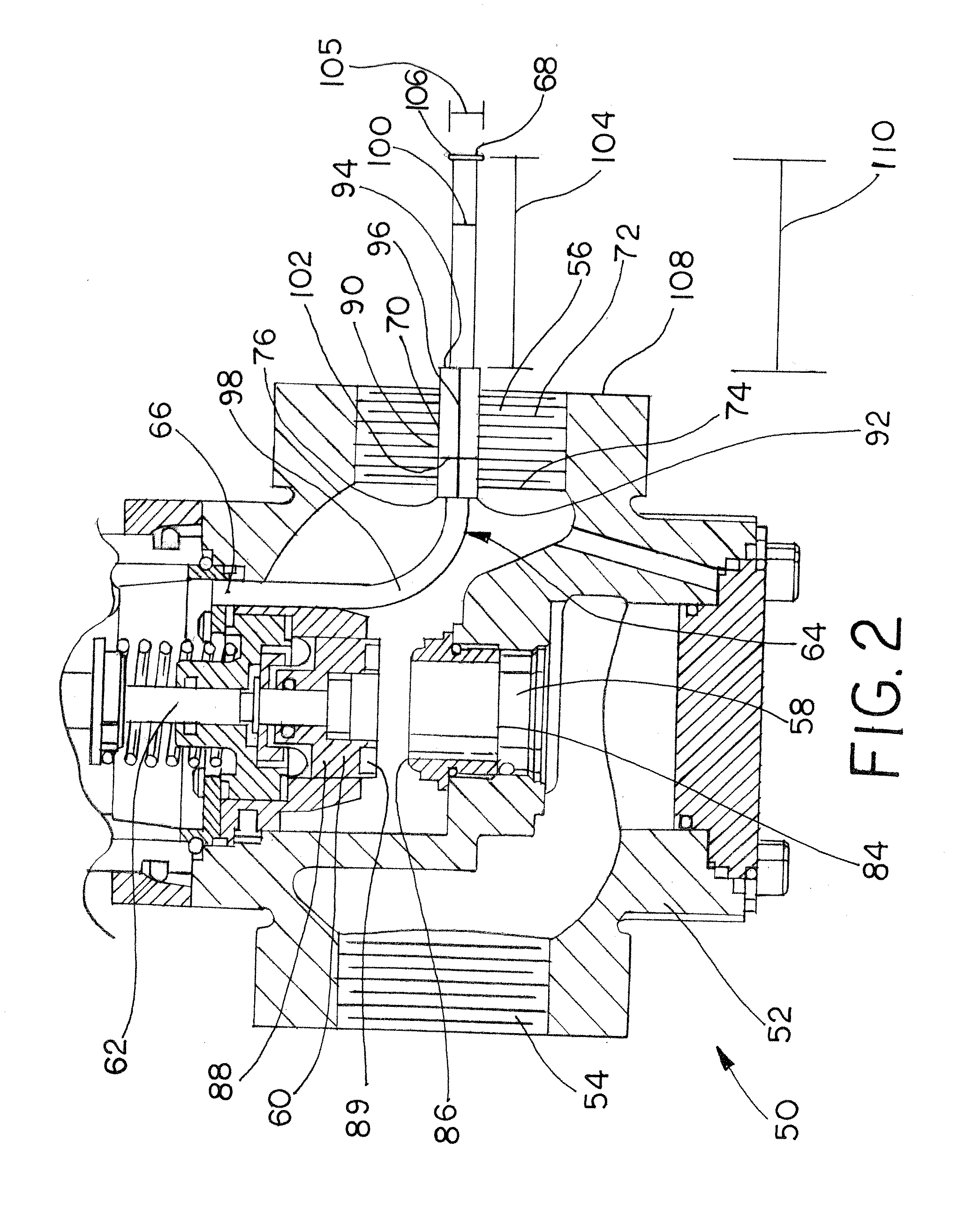
Referring now to the drawings, FIG. 2 illustrates a fluid regulating device assembled in accordance with the teachings of a first disclosed example of the present invention and referred to by the reference numeral 50. The fluid regulating device 50 includes a valve body 52 including a valve inlet 54, a valve outlet 56, and a valve port 58. A control element 60 is shiftably disposed within the valve body 52, such that the control element 60 can be displaced relative to the valve port 58 in order to control the flow of the fluid between the inlet 54 and the outlet 56. The fluid regulating device 50 includes a valve stem 62 which is connected to the control element 60 and to a suitable control assembly in order to control the position of the control element 60. The control assembly may be the control assembly 22 described above with respect to FIG. 1. Consequently, the control assembly 22 will include the same or similar components described above with respect to FIG. 1, such as the va...


PUM


Abstract

A fluid regulating device includes a valve body having an inlet, an outlet, a valve port, and a control element shiftable within the valve body. A control assembly includes an actuator coupled to the control element and includes a diaphragm disposed adjacent a diaphragm chamber. A sense tube has a first end, a second end, and an intermediate portion, the first end positioned to communicate with the diaphragm chamber, the second end disposed adjacent the outlet, and the intermediate portion disposed adjacent an intermediate portion of the outlet. The sense tube includes a shoulder and a flared portion, with the flared portion disposed adjacent the second end.

Description

FIELD OF THE INVENTIONThe present invention relates generally to regulators such as fluid or gas regulators and, more specifically, to a regulator having a pressure registration flow modifier.BACKGROUNDRegulators are commonly employed in fluid or gas distribution systems to control the pressure in the system downstream of the regulator. As is known, the pressure at which a typical gas distribution system supplies gas may vary according to the demands placed on the system, the climate, the source of the supply, and / or other factors. However, most end-user facilities equipped with, for example, gas appliances such as furnaces, ovens, etc., require the gas to be delivered in accordance with predetermined pressure parameters. Therefore, such distribution systems use gas regulators to ensure that the delivered gas meets the requirements of the end-user facilities.Conventional gas regulators generally include a closed-loop control actuator or control assembly for sensing and controlling t...

Claims


Application Information

Patent Timeline
Patent Type & Authority Applications(United States)
IPC IPC(8): F15D1/00
CPCG05D16/0683G05D16/02Y10T137/0318Y10T137/7757Y10T137/7786Y10T137/7787
Inventor FOUST, GREGORY L.CHIZEK, JARED B.MICHNEVITZ, MARK A.NGUYEN, TUNG K.
Owner EMERSON PROCESS MANAGEMENT REGULATOR TECH INC
Learn More