Vehicle location detection device and vehicle location detection method

a technology for vehicle location and detection device, which is applied in the direction of direction finders, measurement devices, instruments, etc., can solve the problems of driving misunderstand and conventional techniques that do not make it possible to detect a location, and achieve the effect of ensuring safe driving

Active Publication Date: 2011-07-21
PANASONIC CORP
View PDF8 Cites 48 Cited by
  • Summary
  • Abstract
  • Description
  • Claims
  • Application Information

AI Technical Summary

Benefits of technology

[0024]The present invention makes it possible to specify the location of the other vehicle even if the other vehicle is hidden behind the obstacle.
[0025]With this, for instance, when the present invention is applied to prevent a co

Problems solved by technology

However, with the techniques proposed in Patent References 1 and 2, in some cases, it is erroneously determined that another vehicle is at a distance farther than an actual distance because a sound pressure attenuation amount is significantly large when an obstacle is between a detection location and a sound source location.
For example, wh

Method used


Image

  • Vehicle location detection device and vehicle location detection method
  • Vehicle location detection device and vehicle location detection method
  • Vehicle location detection device and vehicle location detection method

Examples


embodiment 1

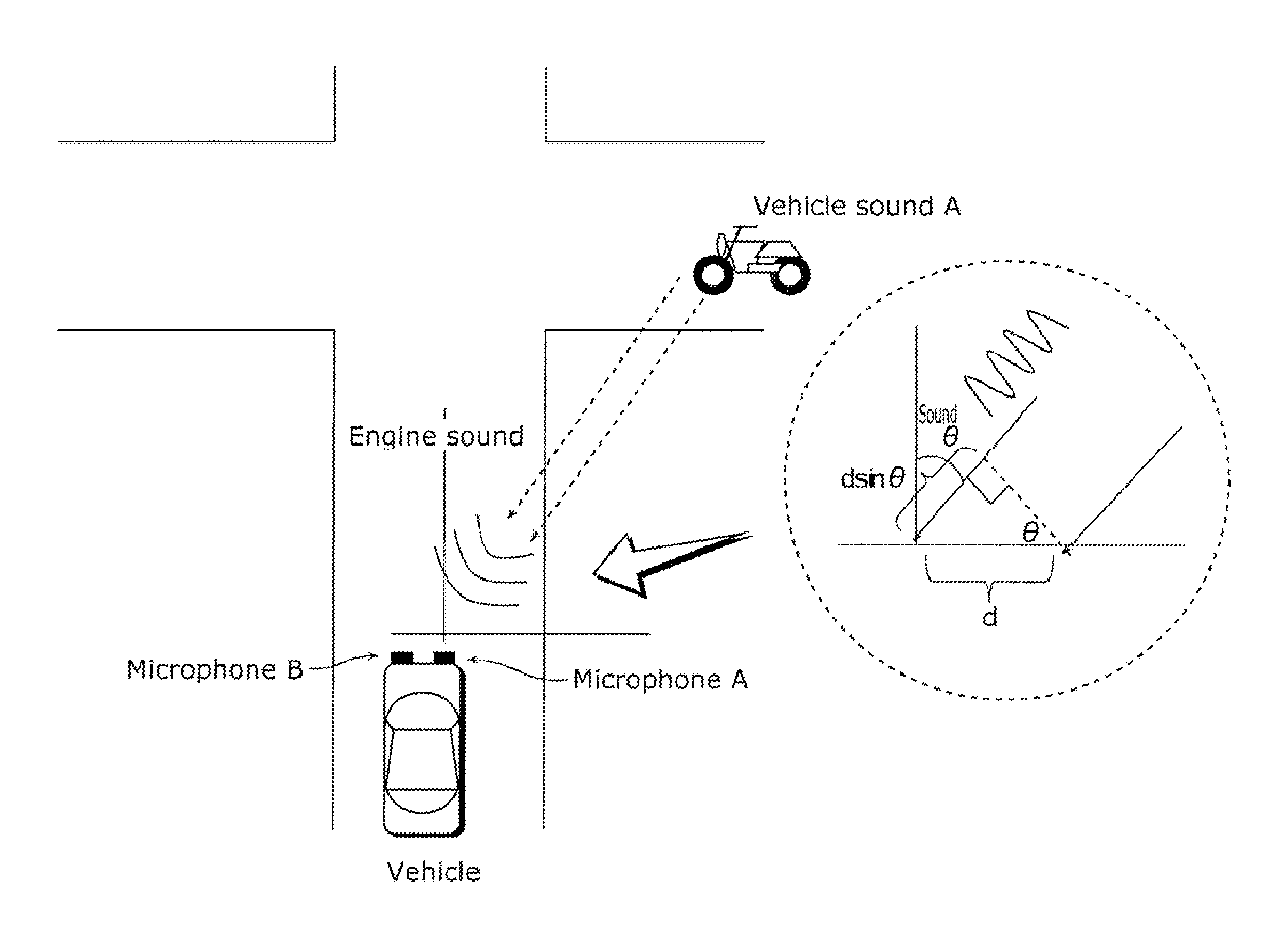
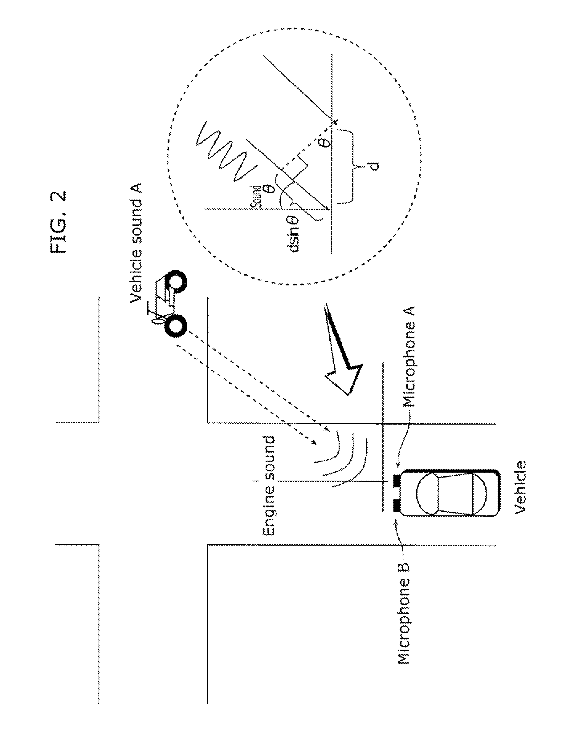
[0059]The following describes a vehicle location detection device according to Embodiment 1 of the present invention. Here, described is a method for specifying a location of another vehicle when there is no obstacle.

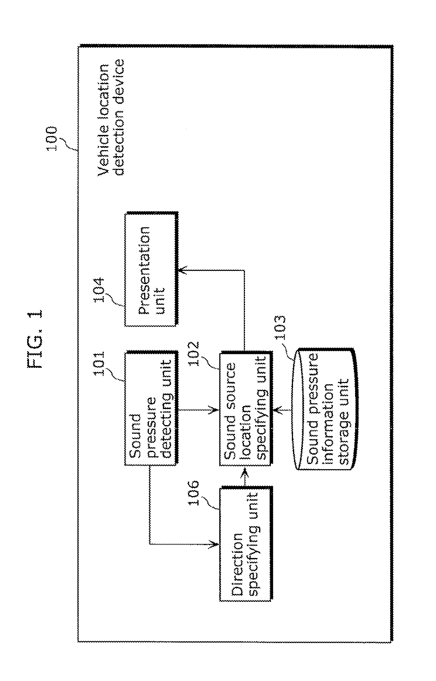
[0060]FIG. 1 is a block diagram showing an entire structure of a vehicle location detection device 100 according to Embodiment 1 of the present invention. The vehicle location detection device 100 according to Embodiment 1 of the present invention is mounted in a vehicle, is a device which detects locations of other vehicles near the vehicle, and includes a sound pressure detecting unit 101, a sound source location specifying unit 102, a sound pressure information storage unit 103, a presentation unit 104, and a direction specifying unit 106.

[0061]The sound pressure detecting unit 101 includes microphones and the like, and detects a value of a sound pressure of another vehicle (i.e., a sound pressure of a vehicle sound arriving at a vehicle) at a detection location (i.e...

embodiment 2

[0086]The following describes a vehicle location detection device according to Embodiment 2 of the present invention.

[0087]Embodiment 2 describes a method for specifying an area where a vehicle in a blind spot is hidden behind an obstacle.

[0088]FIG. 12 is a block diagram showing a vehicle location detection device 200 according to Embodiment 2. The vehicle location detection device 200 is mounted in a vehicle, is a device which detects locations of vehicles near the vehicle, and includes a sound pressure detecting unit 101a, a sound source location specifying unit 102a, a sound pressure information storage unit 103a, a presentation unit 104, a vehicle sound frequency detecting unit 105, a direction specifying unit 106, a vehicle location detecting unit 107, an obstacle information storage unit 108, a diffraction information storage unit 109, and a diffraction location specifying unit 110. Hereinafter, the same reference signs are given to elements that are the same as those in Embod...


PUM


Abstract

The vehicle location detection device includes: a sound source location specifying unit which calculates an attenuation amount of a sound pressure of a vehicle sound by subtracting a sound pressure detected by a sound pressure detecting unit from a sound pressure indicated by vehicle sound pressure information stored in a sound pressure information storage unit, and specifies a location where another vehicle emitting a vehicle sound is predicted to be present, by specifying a sound source location of a sound diffracted by an obstacle which is specified by a diffraction location specifying unit and serves as a diffraction point, based on the calculated attenuation amount, a rule indicating an attenuation amount dependent on a propagation distance of the sound, and a relationship indicated by diffraction information stored in a diffraction information storage unit; and a presentation unit which presents the specified location.

Description

CROSS REFERENCE TO RELATED APPLICATION[0001]This is a continuation application of PCT application No. PCT / JP2010 / 004330 filed on Jul. 1, 2010, designating the United States of America.BACKGROUND OF THE INVENTION[0002](1) Field of the Invention[0003]The present invention relates to vehicle location detection devices which specify, using a vehicle sound of another vehicle, a location of the other vehicle, and in particular to a vehicle location detection device which specifies a location of the other vehicle hidden behind an obstacle.[0004](2) Description of the Related Art[0005]When a vehicle is in operation, detecting other vehicles near or approaching the vehicle is useful for safe driving. Various methods have been conventionally proposed as techniques for detecting such vehicles.[0006]For instance, there is a technique for detecting a sound pressure and a frequency of a sound emitted by a moving object and specifying a distance to the moving object based on the detected sound pre...

Claims


Application Information

Patent Timeline
IPC IPC(8): G08G1/123
CPCG01S3/8083G01S5/18B60W30/08G08G1/16B60W50/14G08G1/04G08G1/165G08G1/166G08G1/167
Inventor YOSHIOKA, MOTOTAKAYOSHIZAWA, SHINICHI
Owner PANASONIC CORP
Why Eureka
Try Eureka