Latch assembly for a connector assembly

a technology of connector assembly and latch assembly, which is applied in the direction of coupling device connection, coupling protective earth/shielding arrangement, coupling/disengagement of coupling parts, etc., can solve the problems of achieving desired electrical transmission performance, unable to meet the requirements of a limited space, and unable to maintain an acceptable termination and assembly process

Active Publication Date: 2011-07-21
BISON PATENT LICENSING LLC
View PDF41 Cites 132 Cited by
  • Summary
  • Abstract
  • Description
  • Claims
  • Application Information

AI Technical Summary

Problems solved by technology

However, such systems are not without disadvantages.
For instance, with increased numbers of contact pairs, and as products become denser, known systems and connectors are challenged to perform wire termination and assemble the connectors.
Difficulties arise in achieving desired electrical transmission performance due to interference and signal degradation, such as from cross-talk between contact pairs.
While some systems attempt to provide electrical isolation between components by surrounding them with materials that effectively provide shielding from cross-talk, providing such shielding in a limited space while maintaining an acceptable termination and assembly process has proven problematic.
Additionally, known systems suffer from problems with accessibility for installation and removal within the system.
The space between neighboring connector assemblies connected to the panels is limited.
Many high density connector assemblies use screw fasteners to retain the connector assemblies to the panel because of the limited space.
However, such systems require a tool, such as a screwdriver, to install and remove the connector assemblies, which increases the installation and removal time.

Method used


Image

  • Latch assembly for a connector assembly
  • Latch assembly for a connector assembly
  • Latch assembly for a connector assembly

Examples


Embodiment Construction

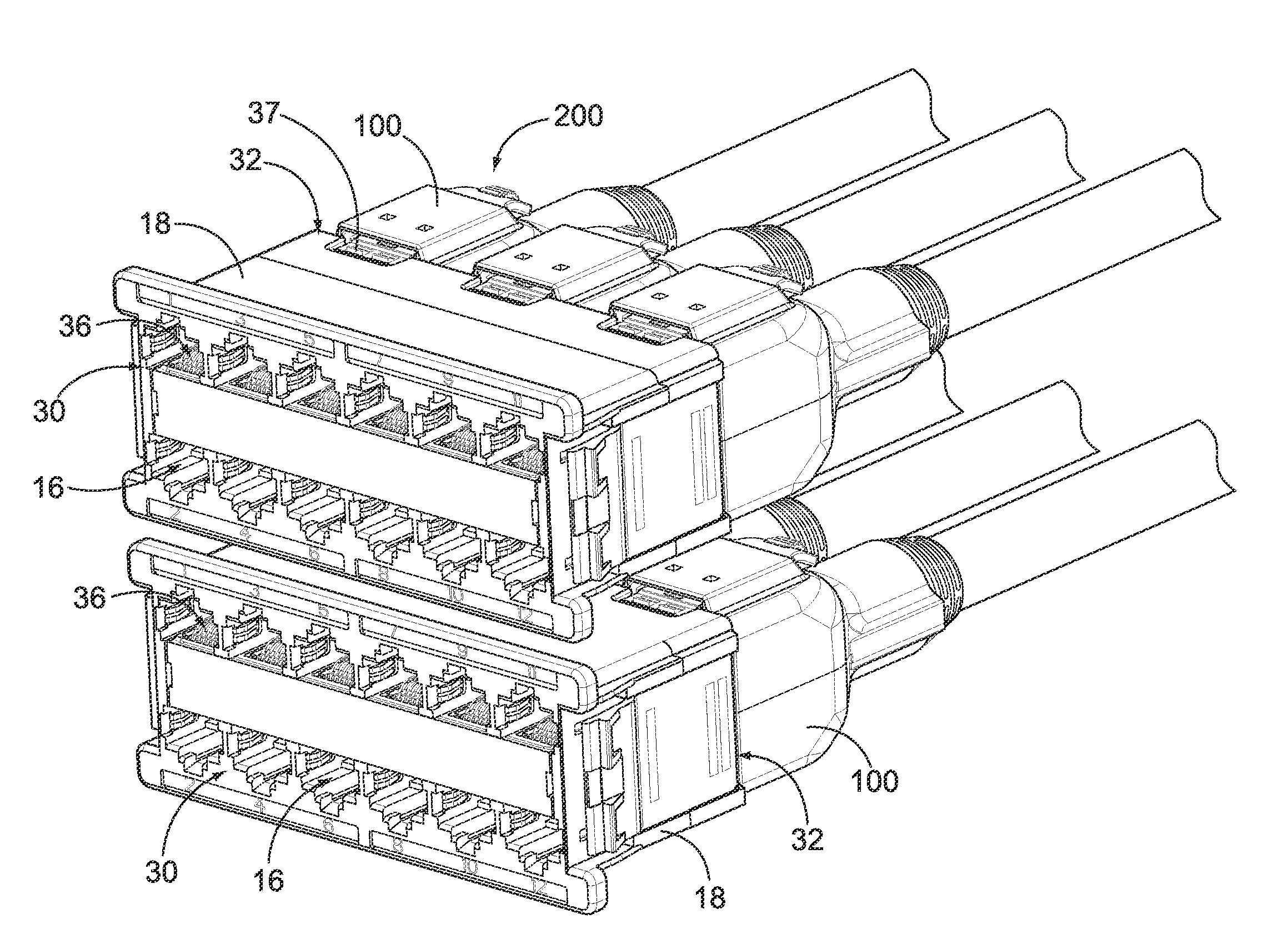
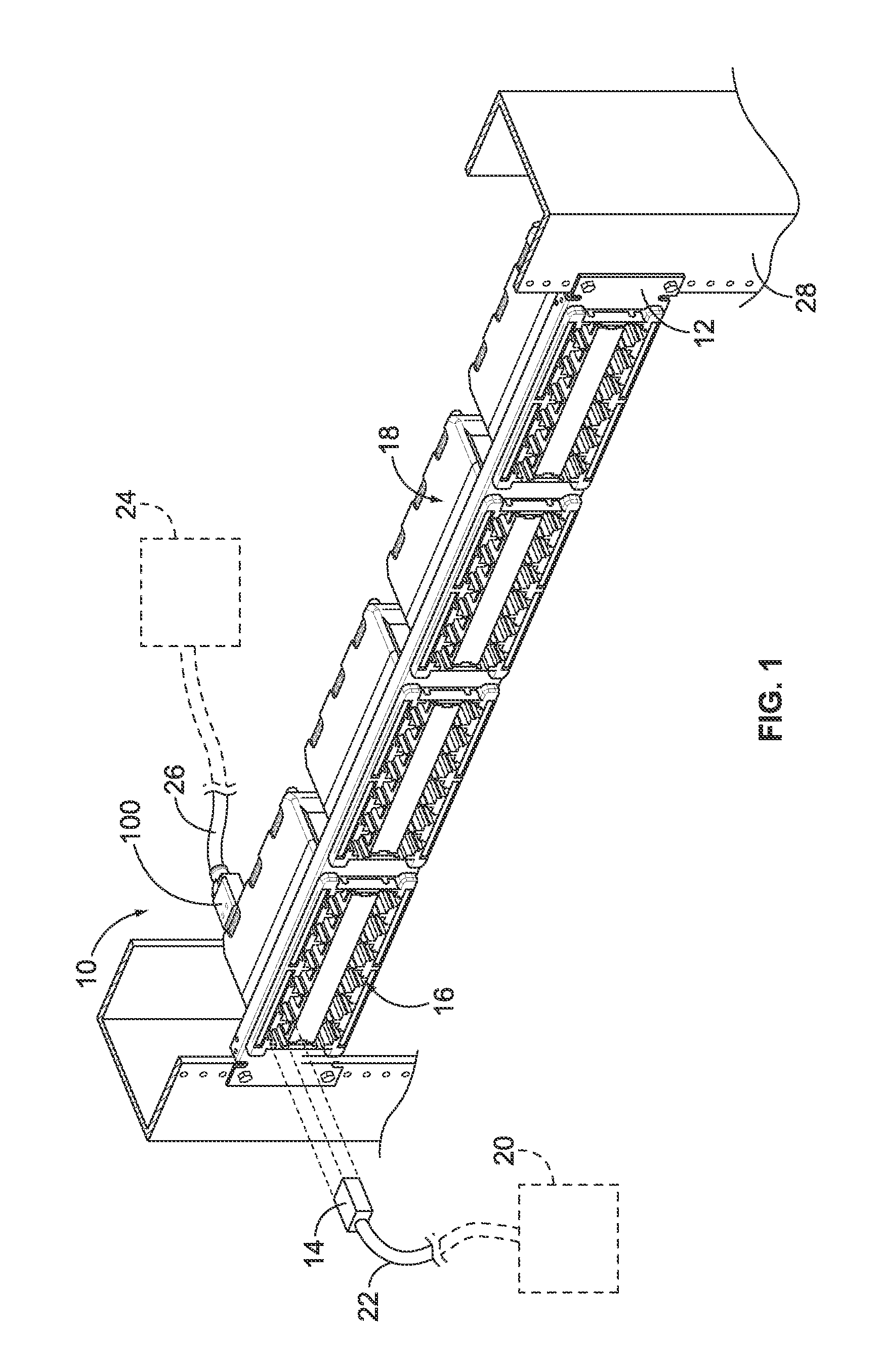
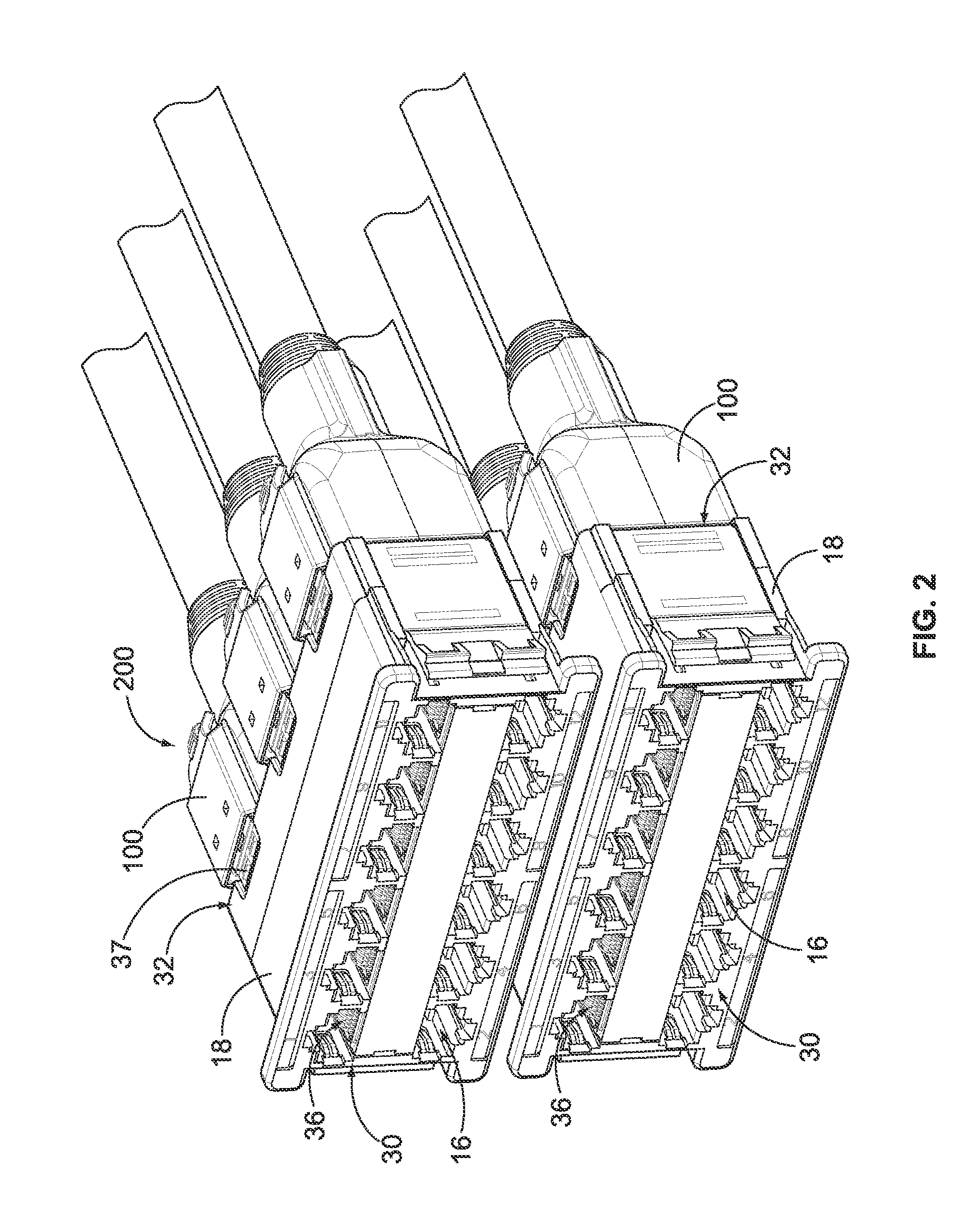
[0019]FIG. 1 is a front perspective view of a portion of a cable interconnect system 10 illustrating a panel 12 and a plurality of cassettes 18 mounted to the panel 12. FIG. 1 also illustrates a modular plug 14 connected to one of the cassettes 18. The cassette 18 comprises an array of receptacles 16 for accepting or receiving the modular plug 14. The cassette 18 represents a multi-port electrical connector, and may be referred to hereinafter as multi-port electrical connector 18 or electrical connector 18.

[0020]The cable interconnect system 10 is utilized to interconnect various equipment, components and / or devices to one another. FIG. 1 schematically illustrates a first device 20 connected to the cassette 18 via a cable 22. The modular plug 14 is attached to the end of the cable 22. FIG. 1 also illustrates a second device 24 connected to the cassette 18 via a cable 26, such as a multi-pair cable having multiple wire pairs. A multi-plug connector assembly 100 is provided at the end...


PUM


Abstract

A connector assembly for mating with a multi-port electrical connector includes a shielded housing having a plurality of discrete shielded plug chambers and a plurality of plugs received in corresponding plug chambers. Each of the plugs are shielded from one another by the shielded housing, and the plugs are configured for simultaneous mating with the multi-port electrical connector, wherein each plug is received in a different port of the electrical connector. The connector assembly also includes a latch assembly coupled to the shielded housing. The latch assembly engages the shielded housing and is configured to engage the multi-port electrical connector to electrically common the shielded housing and the multi-port electrical connector.

Description

BACKGROUND OF THE INVENTION[0001]The subject matter herein relates generally to data communication systems, and more particularly, to connector assemblies for data communication systems.[0002]Data communication systems have many applications, including telecommunications and interconnecting computers over local area networks. Application demands are driving systems to have increased electrical performance while increasing the density of connectivity. Some known systems strive to maximize the number of contact pairs within a connector to make installation orderly and efficient. However, such systems are not without disadvantages. For instance, with increased numbers of contact pairs, and as products become denser, known systems and connectors are challenged to perform wire termination and assemble the connectors. Difficulties arise in achieving desired electrical transmission performance due to interference and signal degradation, such as from cross-talk between contact pairs. While ...

Claims


Application Information

Patent Timeline
Patent Type & Authority Applications(United States)
IPC IPC(8): H01R13/62
CPCH01R13/514H01R13/518H01R13/659H01R2201/04H01R13/6586H01R13/6275
Inventor TOBEY, SHAWN PHILLIP
Owner BISON PATENT LICENSING LLC
Why Eureka
Try Eureka