High Pressure Fuel Injector Seat That Resists Distortion During Welding

a fuel injector seat and welding welding technology, applied in the field of vehicles, can solve the problems of leakage at the seal, uniform welding distortion of the seat, and inability to meet the requirements of welding,

Inactive Publication Date: 2011-07-28
CONTINENTAL AUTOMOTIVE SYST INC
View PDF4 Cites 8 Cited by
  • Summary
  • Abstract
  • Description
  • Claims
  • Application Information

AI Technical Summary

Benefits of technology

[0007]In accordance with another aspect of the invention a method is provided to isolate a seating surface and a guide surface of a valve seat of a fuel injector during a welding process. A valve seat includes a main body having a proximal and a distal end, at least one orifice extending through the main body, a seating surface on the main body constructed and arranged to receive a closure member of a fuel injector such that when the closure member engages the seating surface, the at least one orifice is closed, a guide surface on the main body constructed and arranged to guide movement of the closure member, and an annular wall extending in a cantilever manner from the main body at the distal end thereof and defining an outer peripheral portion of the valve seat. The method includes welding the valve seat to a valve body of a fuel injector so that the annular wall deforms during welding thereby to isolating effects of the welding from the seating surface and the guide surface.

Problems solved by technology

It is noted that distortion by welding is not uniform and the resulting distortion of the seat 14 is thus also not uniform.
This distortion of the seat 14 results in leaks at the seal and non-uniform shrinkage of the guide portion of the seat 14, which cause durability problems of the fuel injector 10.

Method used


Image

  • High Pressure Fuel Injector Seat That Resists Distortion During Welding
  • High Pressure Fuel Injector Seat That Resists Distortion During Welding
  • High Pressure Fuel Injector Seat That Resists Distortion During Welding

Examples


first embodiment

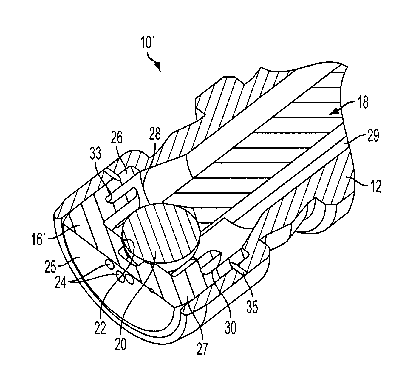
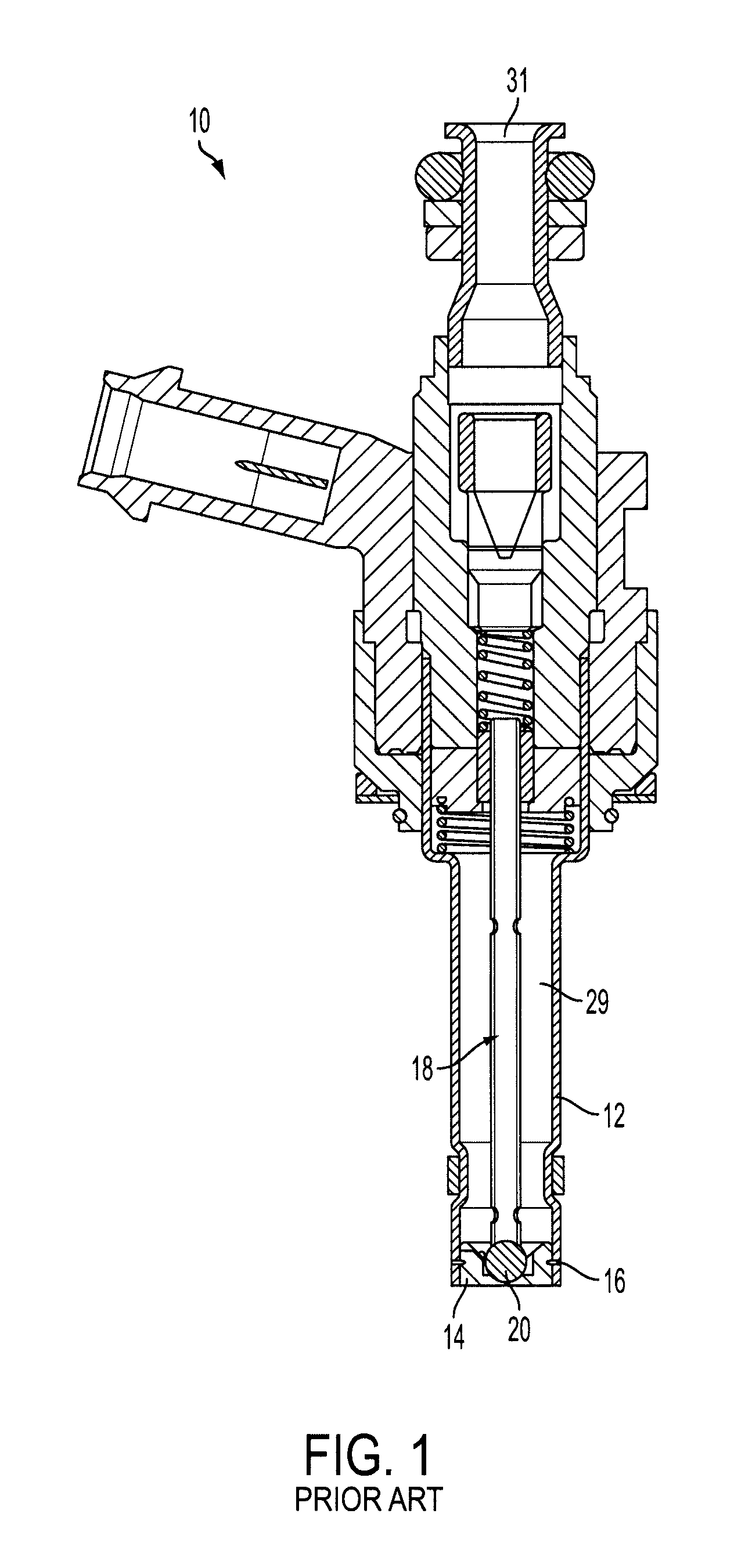
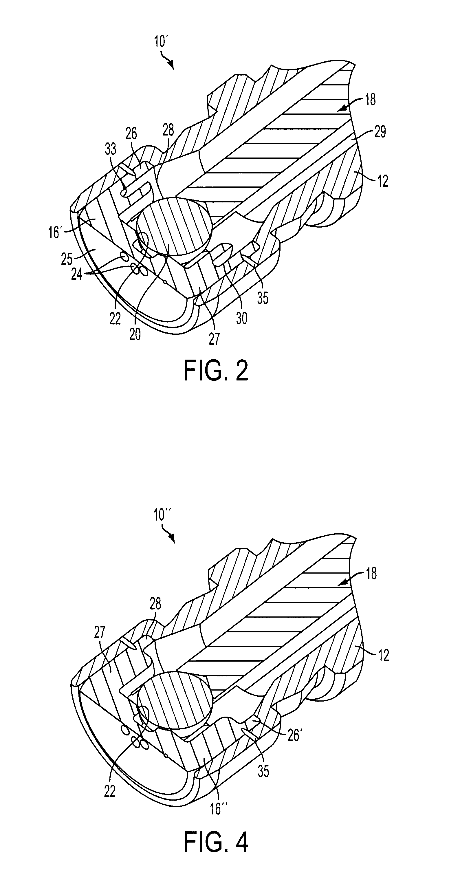
[0014]Referring to FIG. 2, a valve seat 16′ of a gasoline-type, solenoid operated fuel injector 10′ is shown in accordance with a The fuel injector 10′ is of the type shown in FIG. 1, except that the valve seat 16′ is constructed and arranged to resist distortion thereof during welding to the valve body 12 of the injector 10′.

[0015]The valve seat 16′ defines a seating surface 22, which can have a frustoconical or concave shape, facing the interior of the valve body 12. The seating surface 22 includes at least one fuel outlet opening 24 through a proximal end 25 of a main body 27 of the seat 16′. The opening 24 is in communication with an inlet tube 29 for conducting pressurized fuel into the valve body 12 against the seating surface 22. The inlet tube 29 defines an inlet end 31 (see FIG. 1) of the injector 10′ and is typically mounted to a fuel rail (not shown) as is known.

[0016]A closure member, e.g., a spherical valve ball 20, within the injector 10′ is moveable between a first, ...

second embodiment

[0020]FIG. 4 shows the valve seat 16″ provided in a fuel injector 10″. In this embodiment, no groove is provided and the wall 26′ extends from the main body 27 of the seat 16″ in a cantilever manner at the distal end 28 thereof. The wall 26′ has a thickness less than the thickness of each of the seating surface 22 and guide surface 36 (same as in FIG. 3) so that the wall 26′ will deform instead of these surfaces 22 and 34 during welding. As shown in FIG. 4, the weld 35 secures the valve body 12 to the annular wall 26′.


PUM

PropertyMeasurementUnit
displacementaaaaaaaaaa
thicknessaaaaaaaaaa
pressureaaaaaaaaaa

Abstract

A valve seat (16′) for a fuel injector (10) includes a main body (27) having a proximal and a distal end with at least one orifice (24) extending through the main body. A seating surface (22) is provided on the main body to receive a closure member (20) of a fuel injector such that when the closure member engages the seating surface, the at least one orifice is closed. A guide surface (36) is provided on the main body to guide movement of the closure member. An annular wall (26) extends in a cantilever manner from the main body at the distal end thereof and defines an outer peripheral portion of the valve seat. The wall is constructed and arranged to deform during welding at the wall so as to isolate effects of the welding from the seating surface and the guide surface.

Description

FIELD OF THE INVENTION[0001]The invention relates to fuel injectors for vehicles and, more particularly, to a high pressure fuel injector seat that resists distortion during welding when assembled.BACKGROUND OF THE INVENTION[0002]With reference to FIG. 1, a typical construction of a gasoline fuel injector, generally indicated at 10, includes a valve body 12, in which a valve seat 14 is hermetically secured via a weld 16. The valve seat 14 has multiple functions such as to provide 1) a guide for the armature tube ball assembly, generally indicated at 18, 2) a conical sealing surface on which the ball 20 sits, and 3) orifice holes for spray generation.[0003]The valve seat 14 is a machined and ground part and is fixed to the valve body 12 via the hermitic weld 16 through the valve body wall and into the valve seat 14. During this operation, the material that was molten during the weld process shrinks during cooling causing distortion of the seat 14.[0004]The distortion imposed on the c...

Claims


Application Information

Patent Timeline
Patent Type & Authority Applications(United States)
IPC IPC(8): F02M51/00B21K1/24
CPCF02M51/0675F02M61/12F02M61/1813Y10T29/49409F02M61/1886F02M2200/03F02M2200/8084F02M61/188
Inventor SPIERS, DEAN LEIGHIMOEHL, WILLIAM J.
Owner CONTINENTAL AUTOMOTIVE SYST INC
Why Eureka
Try Eureka