Extreme ultraviolet light source apparatus

a light source and ultraviolet light technology, applied in the field of extreme ultraviolet light source apparatus, can solve the problems of difficult to know whether the window b>, laser beam focusing optics, variation or reduction in and achieve the effect of rapid action against variation or reduction of the generation efficiency of euv ligh

Active Publication Date: 2011-07-28
GIGAPHOTON
View PDF5 Cites 19 Cited by
  • Summary
  • Abstract
  • Description
  • Claims
  • Application Information

AI Technical Summary

Benefits of technology

[0031]Accordingly, in view of the above problem, an object of the present invention is to provide an extreme ultraviolet light source apparatus in which it is possible to take a rapid action against reduction or variation of an EUV light generation efficiency caused by deterioration or the like of a window and / or a laser beam focusing optics in an EUV light generation chamber.

Problems solved by technology

However, since the laser beam 120 is focused onto the plasma generation position (onto the path of the target material) within the EUV light generation chamber 102, there arises a problem that it is difficult to know whether the window 106 or the laser beam focusing optics 104 is deteriorated or not and to take a rapid response action (replacement of the optical element).
Thereby, instability of the plasma generation is invited finally resulting in variation or reduction in the generation efficiency of the EUV light 121.
However, since the laser beam 120 is focused to the inside of the EUV light generation chamber 102 (plasma generation position), there is a problem that it is difficult to know whether the focusing position of the laser beam 120 is shifted or not, and to take a rapid response action (readjustment of the alignment in the laser beam focusing optics 104).

Method used


Image

  • Extreme ultraviolet light source apparatus
  • Extreme ultraviolet light source apparatus
  • Extreme ultraviolet light source apparatus

Examples


first embodiment

[0086]Next, an EUV light source apparatus according to a first embodiment of the present invention will be described.

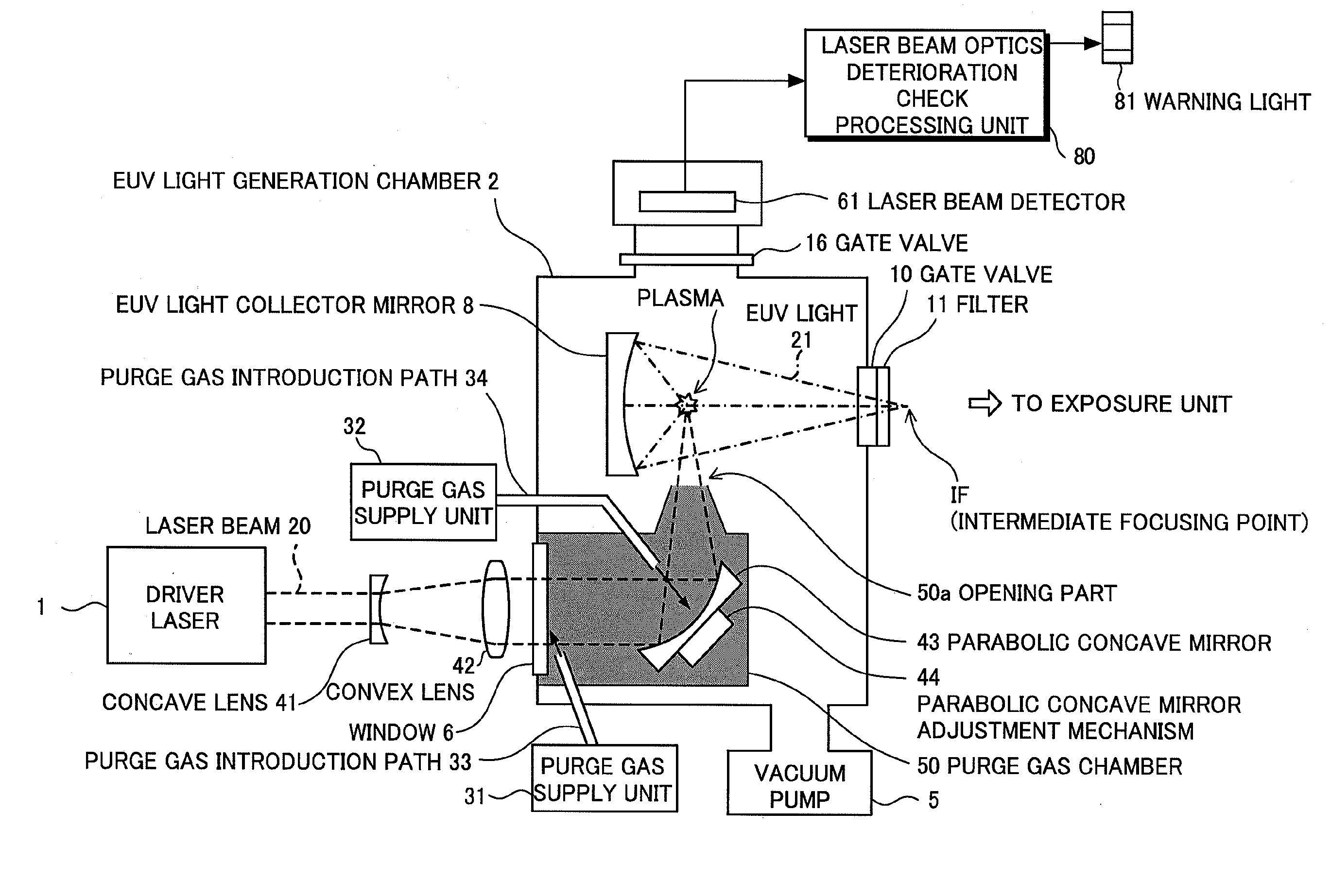
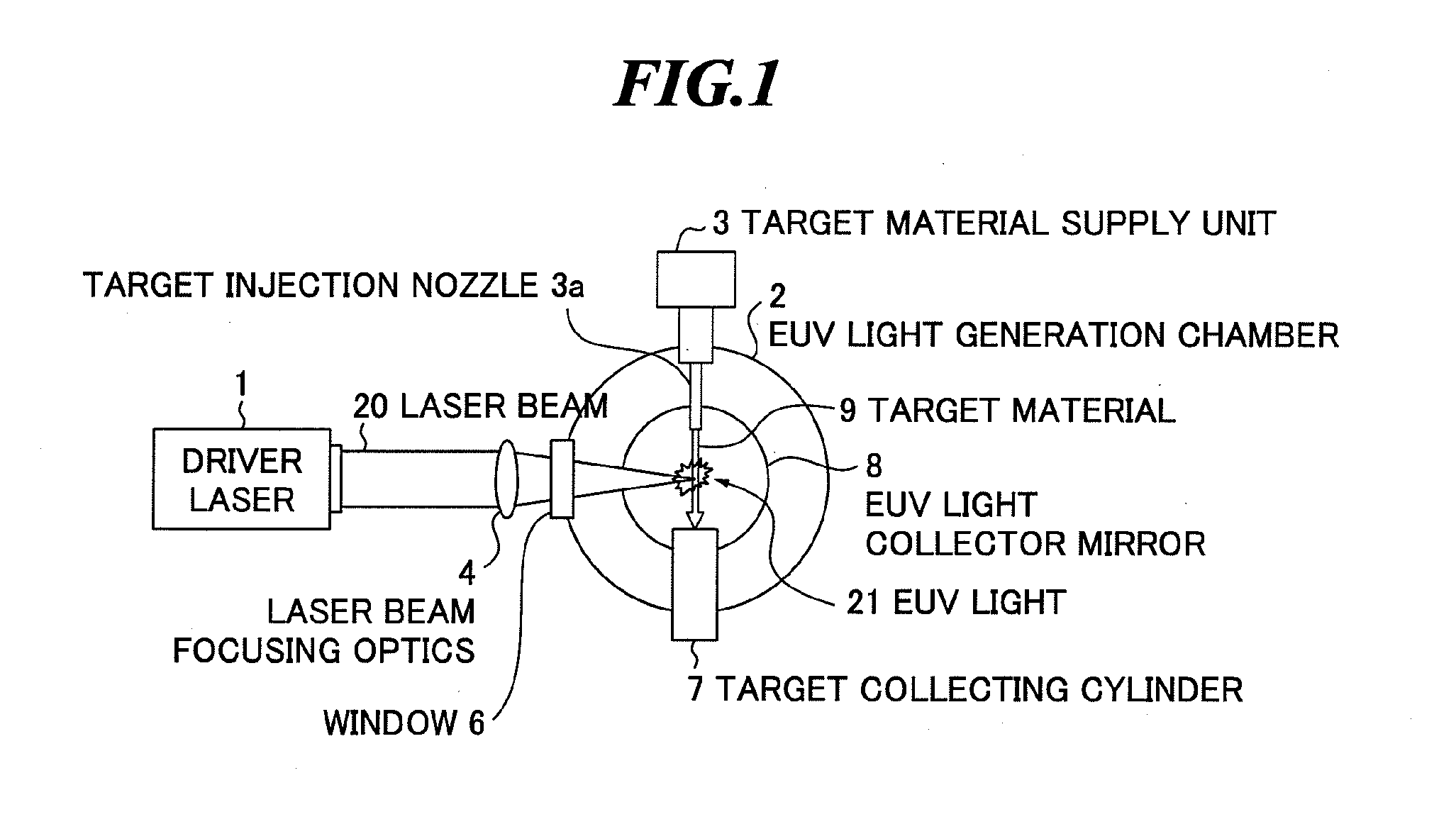
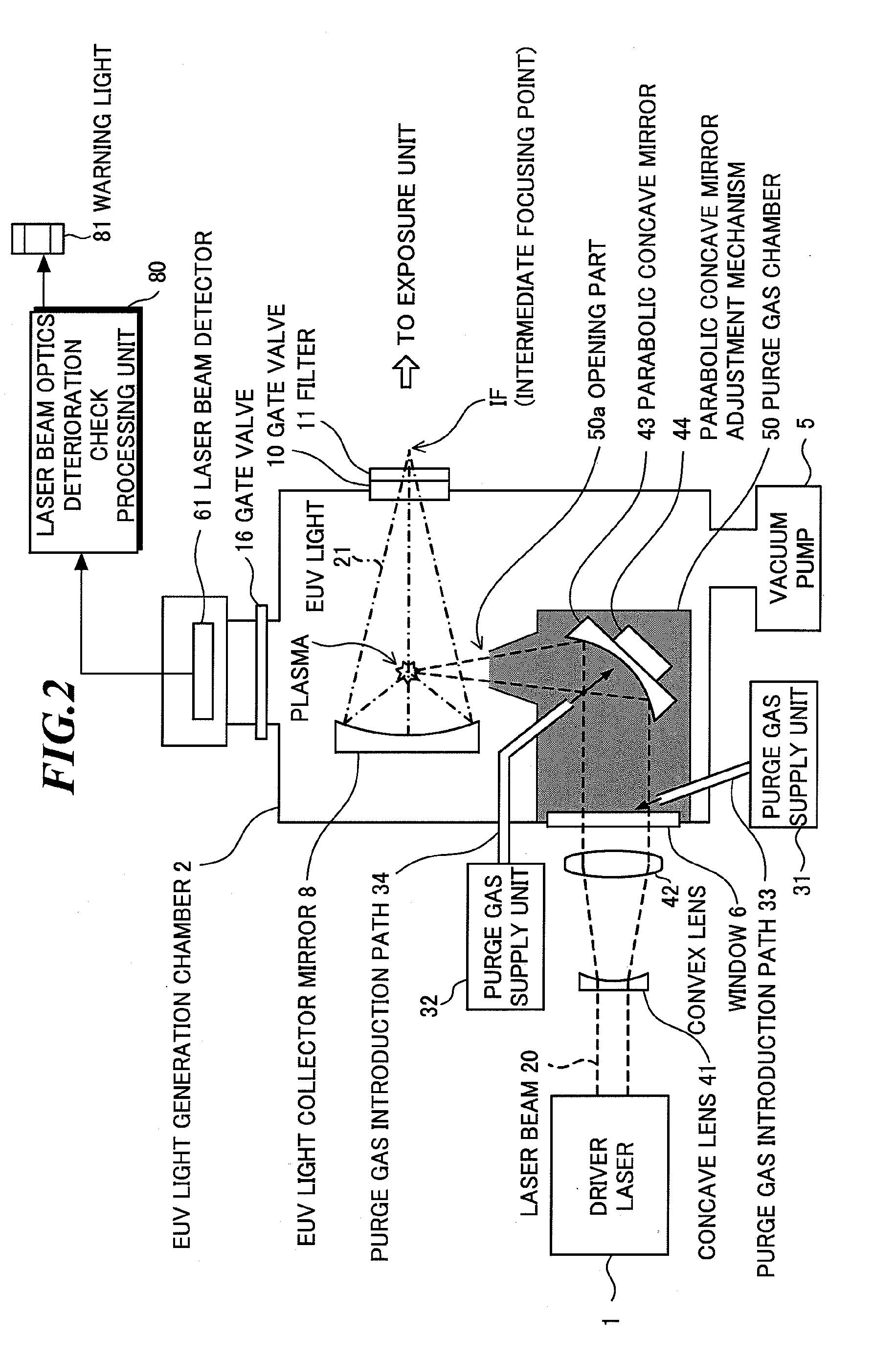
[0087]FIG. 2 and FIG. 3 are schematic diagrams showing the EUV light source apparatus according to the present embodiment. FIG. 2 is a schematic diagram showing a state when the EUV light source apparatus according to the present embodiment generates the EUV light, and FIG. 3 is a schematic diagram showing a state when the EUV light source apparatus according to the present embodiment does not generate the EUV light. Note that FIG. 2 and FIG. 3 omit the target material supply unit 3 and the target material collecting cylinder 7 (refer to FIG. 1) from the drawings, and the target material is assumed to be injected in the direction perpendicular to the page.

[0088]First, mainly with reference to FIG. 2, the operation of the EUV light source apparatus according to the present embodiment will be described for a case of the EUV light generation, and then, mainly with refere...

second embodiment

[0112]Next, an EUV light source apparatus according to a second embodiment of the present invention will be described.

[0113]FIG. 6 and FIG. 7 are schematic diagrams showing the EUV light source apparatus according to the present embodiment. FIG. 6 is a schematic diagram showing a state when the EUV light source apparatus according to the present embodiment generates the EUV light, and FIG. 7 is a schematic diagram showing a state when the EUV light source apparatus according to the present embodiment does not generate the EUV light. Note that FIG. 6 and FIG. 7 omit the target material supply unit 3 and the target material collecting cylinder 7 (refer to FIG. 1) from the drawings, and the target material is assumed to be injected in the direction perpendicular to the page.

[0114]As shown in FIG. 6 and FIG. 7, this EUV light source apparatus further includes a temperature sensor 82 which is added to the above described EUV light source apparatus according to the first embodiment (refer...

third embodiment

[0123]Next, an EUV light source apparatus according to a third embodiment of the present invention will be described.

[0124]FIG. 9 and FIG. 10 are schematic diagrams showing the EUV light source apparatus according to the present embodiment. FIG. 9 is a schematic diagram showing a state when the EUV light source apparatus according to the present embodiment generates the EUV light, and FIG. 10 is a schematic diagram showing a state when the EUV light source apparatus according to the present embodiment does not generate the EUV light. Note that FIG. 9 and FIG. 10 omit the target material supply unit 3 and the target material collecting cylinder 7 (refer to FIG. 1) from the drawings, and the target material is assumed to be injected in the direction perpendicular to the page.

[0125]As shown in FIG. 9 and FIG. 10, this EUV light source apparatus is further provided with a convex lens 63 focusing the laser beam having passed through the gate valve 16 in addition to the above described EU...


PUM


Abstract

An EUV light source apparatus can reliably detect and accurately judge deterioration of an optical element in a laser beam focusing optics disposed within an EUV light generation chamber. This EUV light source apparatus includes: the EUV light generation chamber; a target material supply unit; an EUV light collector mirror; a driver laser; a window; a parabolic mirror which focuses collimated laser beam by reflection and is disposed within the EUV light generation chamber; an energy detector detecting energy of the laser beam diffused without being applied to a target material after being focused by the laser beam focusing optics when the EUV light is not generated; and a processing unit for judging the deterioration of the window and the parabolic mirror according to the laser beam energy detected by the energy detector.

Description

BACKGROUND OF THE INVENTION[0001]1. Field of the Invention[0002]The present invention relates to an LPP (laser produced plasma) type EUV (extreme ultraviolet) light source apparatus generating extreme ultraviolet light which is used for exposing a semiconductor wafer or the like.[0003]2. Description of a Related Art[0004]Recently, along with a finer semiconductor process, optical lithography has been making a rapid progress for realizing a finer pattern, and is now required to realize a fine process at 60 nm through 45 nm and further a fine process at 32 nm and beyond in the next generation. Accordingly, it is expected to develop, for example, an exposure equipment using a combination of an EUV light source generating extreme ultraviolet (EUV) light with a wavelength of approximately 13 nm and a reduced projection reflective system in order to cope with the fine process at 32 nm and beyond.[0005]There are three types of EUV light sources including an LPP (laser produced plasma) ligh...

Claims


Application Information

Patent Timeline
Patent Type & Authority Applications(United States)
IPC IPC(8): H05G2/00
CPCH05G2/008H05G2/003
Inventor MORIYA, MASATOABE, TAMOTSUSUGANUMA, TAKASHISOMEYA, HIROSHIYABU, TAKAYUKISUMITANI, AKIRAWAKABAYASHI, OSAMU
Owner GIGAPHOTON
Why Eureka
Try Eureka