Fixing device and image forming apparatus including same

a technology of fixing device and fixing device, which is applied in the direction of electrographic process apparatus, instruments, optics, etc., can solve the problems of uneven or faulty fixing of output images, and difficult dispersal of heat of metal parts at an area away from the nip

Active Publication Date: 2011-07-28
RICOH KK
View PDF95 Cites 106 Cited by
  • Summary
  • Abstract
  • Description
  • Claims
  • Application Information

AI Technical Summary

Benefits of technology

[0009]In an aspect of this disclosure, there is provided an improved fixing device including an endless, flexible fixing member, a pressing member, a stationary member, a substantially cylindrical metal member, flanges, a first heater, and a second heater. The fixing member is rotatably provided in the fixing device to heat a toner image thereon. The pressing member is rotatably pressed against an outer circumferential surface of the fixing member to form a nip between the pressing member and the fixing member. The stationary member is fixedly disposed at an inner circumferential surface side of the fixing member and pressed by the pressing member with the fixing member interposed between the stationary member and the pressing member. The substantially cylindrical metal member is f

Problems solved by technology

Whether such thermal deformation occurs in a limited area or over a relatively large area of the metal member, it affects the size of a clearance between the fixing belt and the metal member.
Consequently, the fixing belt may be unevenly or insufficiently heated, causing uneven or faulty fixing of an output image.
In particular, in a case in which the stationary member is press

Method used


Image

  • Fixing device and image forming apparatus including same
  • Fixing device and image forming apparatus including same
  • Fixing device and image forming apparatus including same

Examples


Embodiment Construction

[0024]In describing embodiments illustrated in the drawings, specific terminology is employed for the sake of clarity. However, the disclosure of this patent specification is not intended to be limited to the specific terminology so selected and it is to be understood that each specific element includes all technical equivalents that operate in a similar manner and achieve similar results.

[0025]Although the exemplary embodiments are described with technical limitations with reference to the attached drawings, such description is not intended to limit the scope of the invention and all of the components or elements described in the exemplary embodiments of this disclosure are not necessarily indispensable to the present invention.

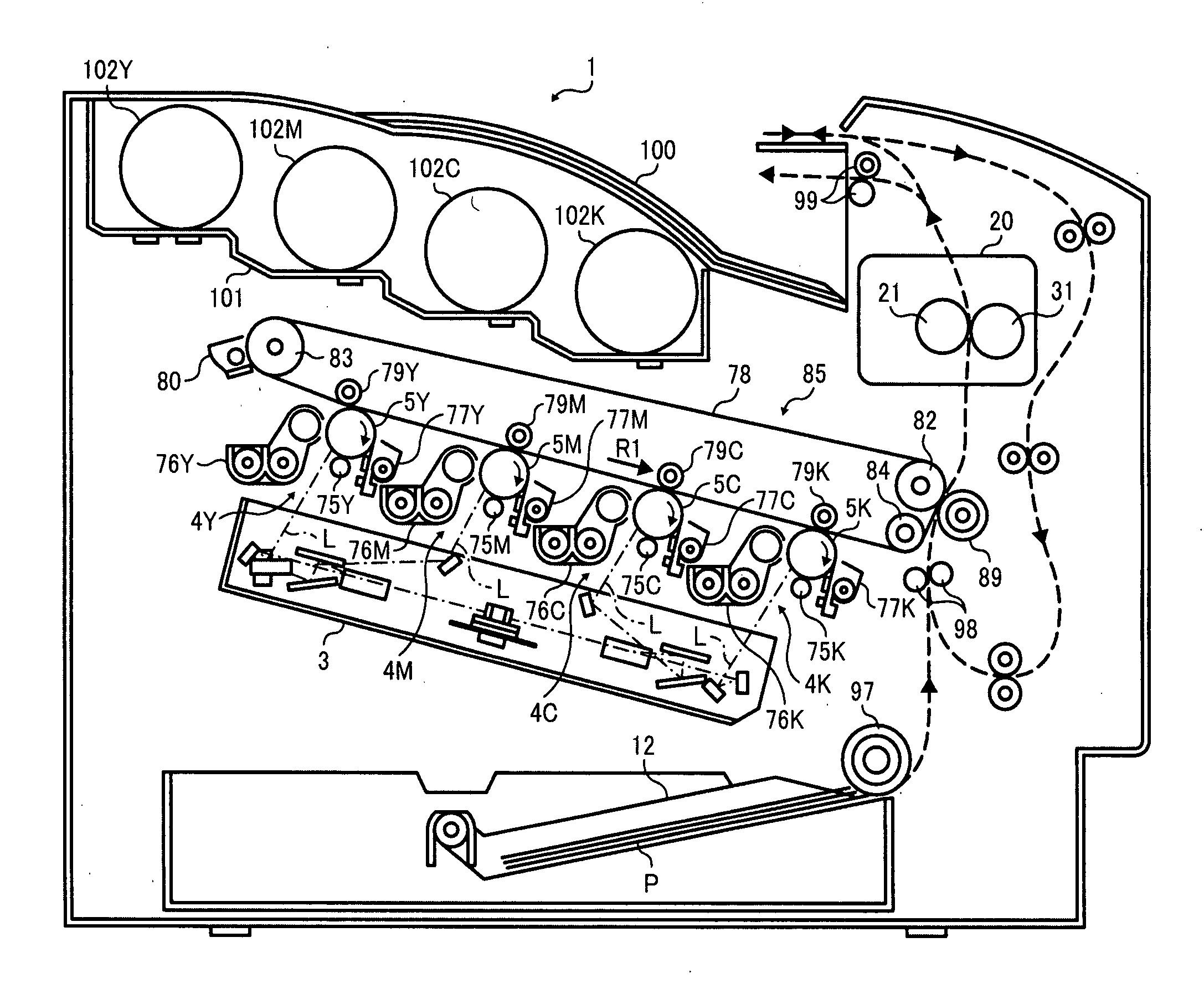
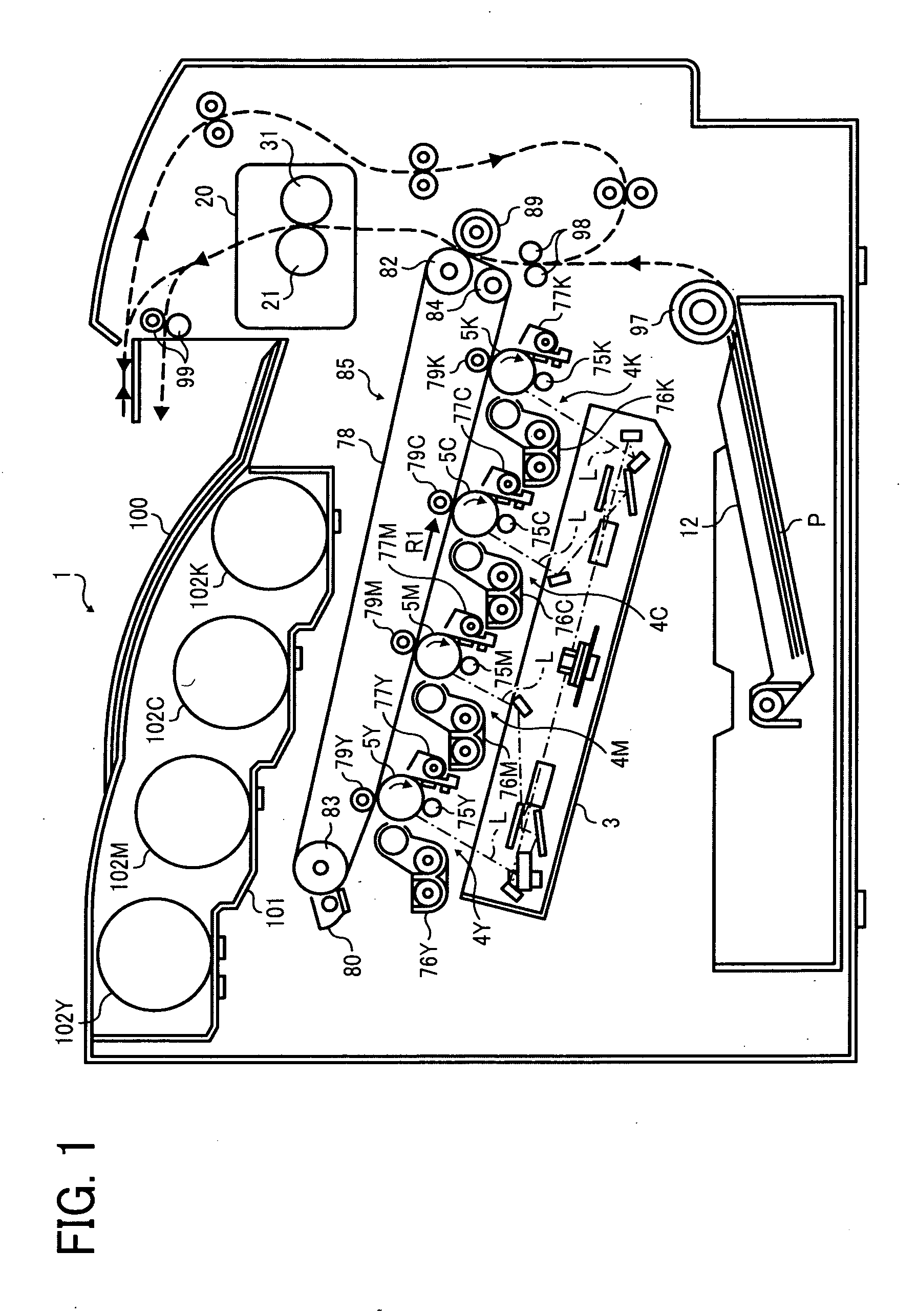
[0026]Referring now to the drawings, wherein like reference numerals designate identical or corresponding parts throughout the several views, in particular to FIG. 1, an image forming apparatus 1 according to an exemplary embodiment of the present disclosure...


PUM


Abstract

A fixing device includes a fixing member, a pressing member, a stationary member, a metal member, flanges, a first heater, and a second heater. The pressing member is rotatably pressed against an outer circumferential surface of the fixing member to form a nip therebetween. The metal member is fixedly disposed opposite an inner circumferential surface of the fixing member over an area other than the nip. The flanges are disposed at axial edges of the metal member in contact with an inner circumferential surface of the metal member. The first heater is disposed opposite the inner circumferential surface of the metal member to heat an axial middle portion of the metal member. The second heater is disposed opposite the inner circumferential surface of the metal member to heat axial end portions of the metal member. The first heater is disposed farther from the nip than the second heater.

Description

CROSS-REFERENCE TO RELATED APPLICATIONS[0001]The present patent application claims priority pursuant to 35 U.S.C. §119 from Japanese Patent Application No. 2010-013963, filed on Jan. 26, 2010 in the Japan Patent Office, which is incorporated herein by reference in its entirety.BACKGROUND OF THE DISCLOSURE[0002]1. Field of the Disclosure[0003]Exemplary embodiments of the present disclosure relate to an image forming apparatus, such as a copier, a printer, a facsimile machine, or a multi functional device having at least two of the foregoing capabilities, and a fixing device employed in the image forming apparatus.[0004]2. Description of the Background Art[0005]Image forming apparatuses, such as copiers, facsimile machines, printers, or multifunction apparatuses having at least two of copying, printing, scanning, and facsimile capabilities, typically form an image on a recording medium according to image data. In such an image forming apparatus, for example, a charger uniformly charge...

Claims


Application Information

Patent Timeline
IPC IPC(8): G03G15/20
CPCG03G2215/2035G03G15/2064
Inventor ISHIGAYA, YASUNORISHINSHI, AKIRAHASEGAWA, KENICHIYOSHINAGA, HIROSHIYAMASHINA, RYOTA
Owner RICOH KK
Why Eureka
Try Eureka