Apparatus for screen location control of flexible display

Active Publication Date: 2011-08-04
PANTECH CORP
View PDF8 Cites 200 Cited by
  • Summary
  • Abstract
  • Description
  • Claims
  • Application Information

AI Technical Summary

Benefits of technology

[0008]Exemplary embodiments of the present invention provide an apparatus to control an image output position of a flexible display, capable of moving a position of a

Problems solved by technology

Therefore, there are problems in accurately viewi

Method used


Image

  • Apparatus for screen location control of flexible display
  • Apparatus for screen location control of flexible display
  • Apparatus for screen location control of flexible display

Examples


Embodiment Construction

[0028]Exemplary embodiments now will be described more fully hereinafter with reference to the accompanying drawings, in which exemplary embodiments are shown. This disclosure may, however, be embodied in many different forms and should not be construed as limited to the exemplary embodiments set forth therein. Rather, these exemplary embodiments are provided so that this disclosure will be thorough, and will fully convey the scope of this disclosure to those skilled in the art. In the description, details of well-known features and techniques may be omitted to avoid unnecessarily obscuring the presented embodiments.

[0029]The terminology used herein is for the purpose of describing particular embodiments only and is not intended to be limiting of this disclosure. As used herein, the singular forms “a”, “an” and “the” are intended to include the plural forms as well, unless the context clearly indicates otherwise. Furthermore, the use of the terms a, an, etc. does not denote a limita...


PUM


Abstract

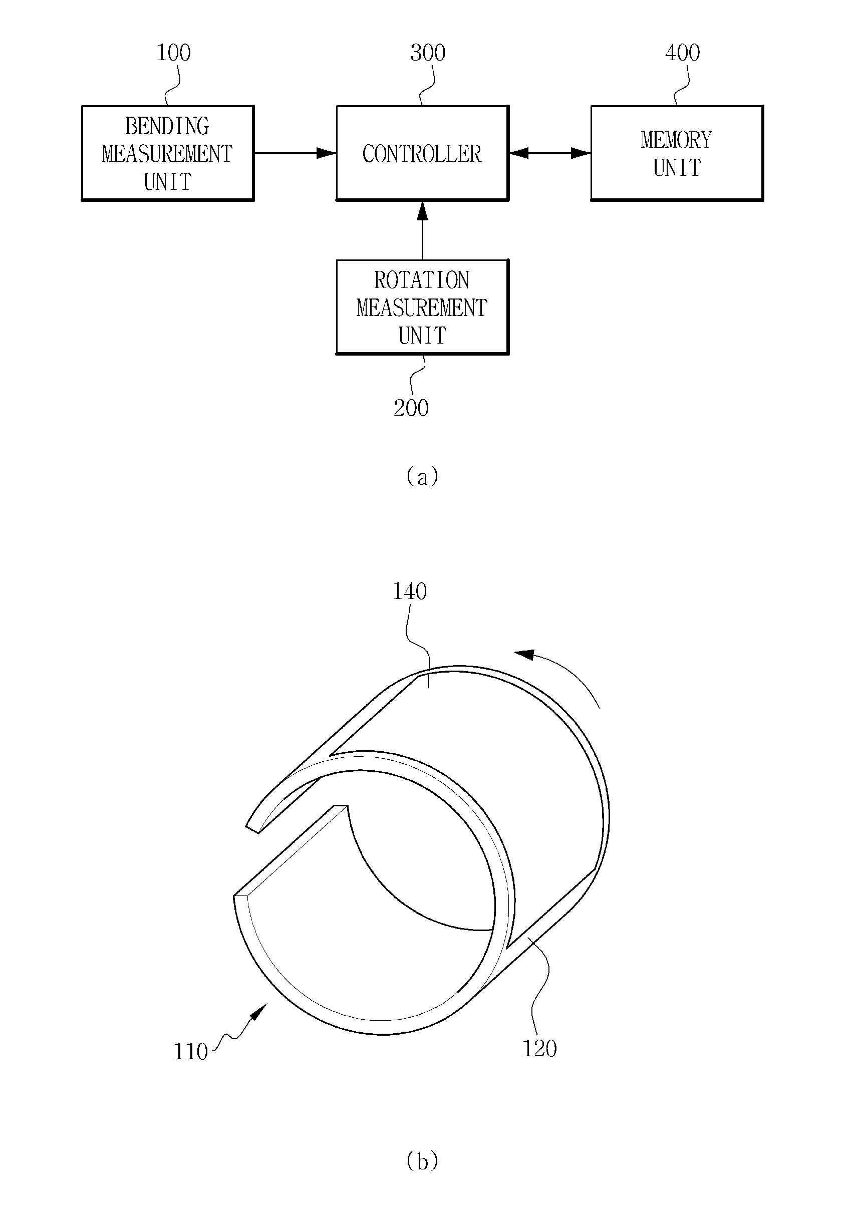
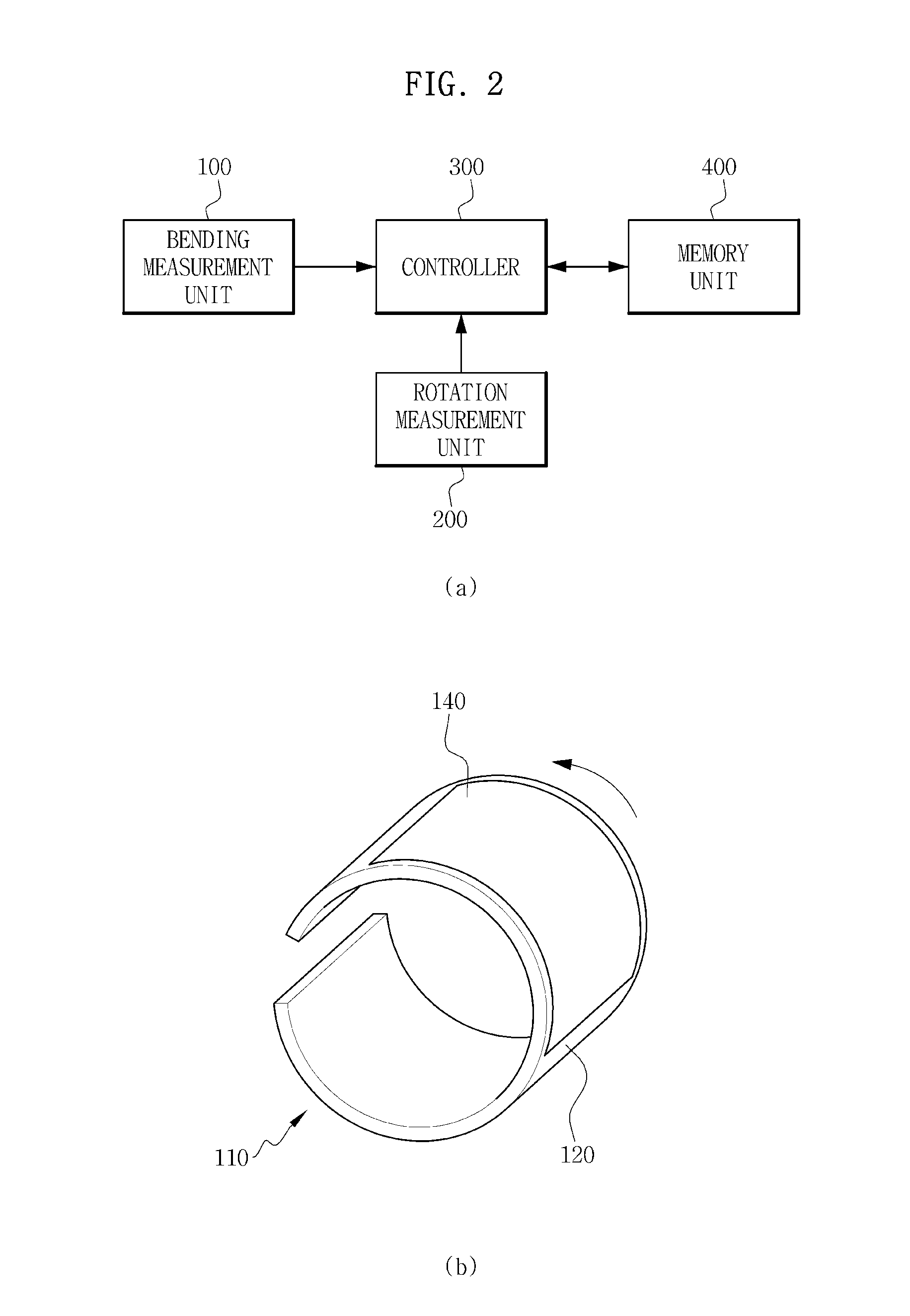
The apparatus to control an image output position of a flexible display moves a position of an image output area in a screen area when the flexible display is rotated. The apparatus may include: a bending measurement unit to measure a bending degree of the flexible display; a rotation measurement unit to measure a rotation degree and a rotation direction of the flexible display; and a controller to output an image at an image output area, and move a position of the image output area.

Description

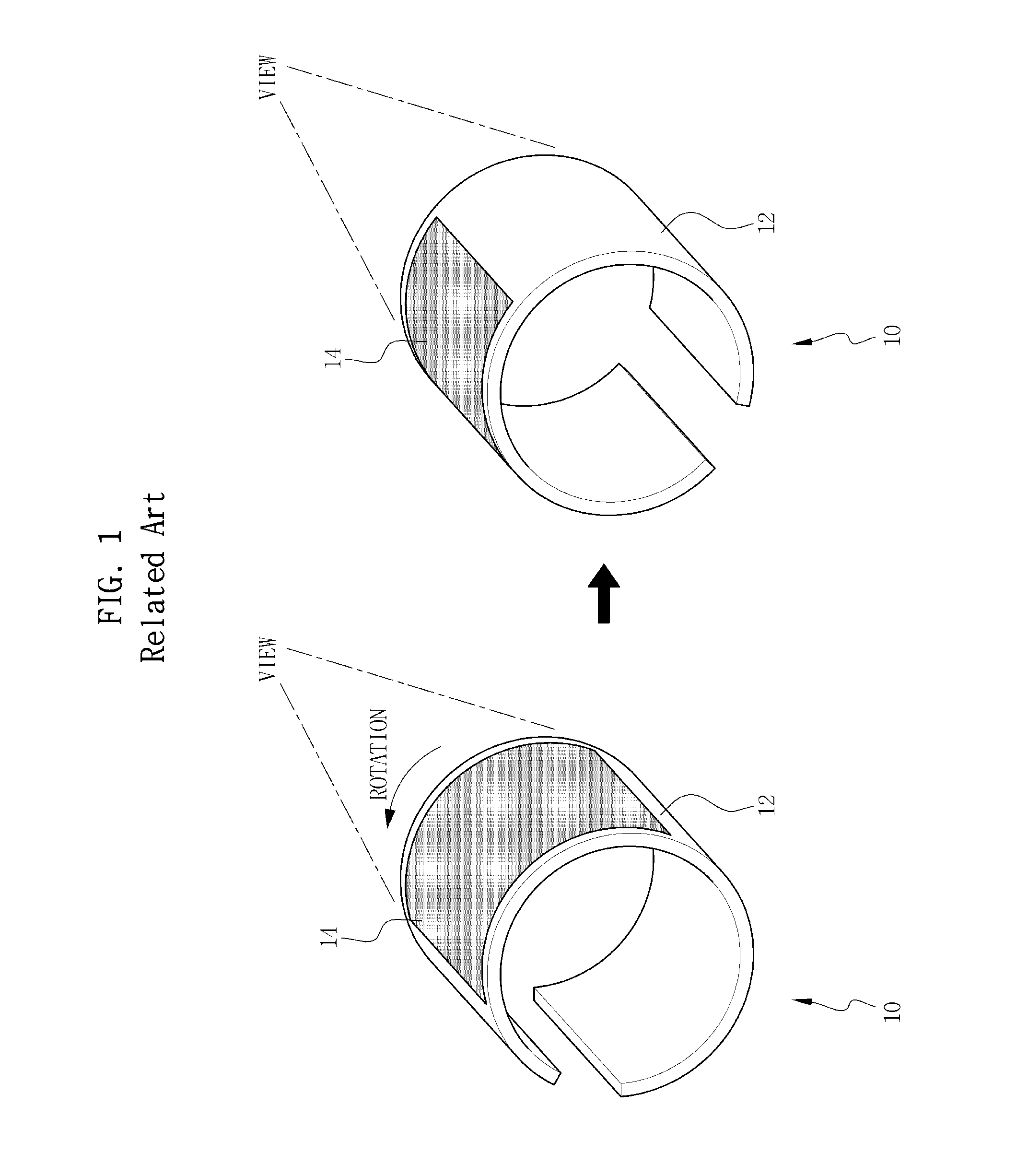
CROSS-REFERENCE TO RELATED APPLICATION[0001]This application claims priority from and the benefit of Korean Patent Application No. 10-2010-0008586, filed on Jan. 29, 2010, which is hereby incorporated by reference for all purposes as if fully set forth herein.BACKGROUND[0002]1. Field[0003]This disclosure relates to an apparatus to control an image output position of a flexible display.[0004]2. Discussion of the Background[0005]A flexible display is a display device having the property of being easily bent and generally includes a screen area in which a number of display elements for outputting an image are distributed on a surface of the flexible display.[0006]As illustrated in FIG. 1, a position of an image output area 14 is fixed at a particular position on a screen area 12 of a flexible display 10. Therefore, in a case where an outer shape of the flexible display 10 is bent and the image output area 14 forms a curved surface, the image output area 14 is rotated by a rotating oper...

Claims


Application Information

Patent Timeline
IPC IPC(8): G09G5/00G06F3/041G06F3/048G06F3/0488
CPCG06F3/0488G06F2200/1637G06F3/147G09G2354/00G09G2340/0464G09G2380/02G06F1/1652G06F3/0414
Inventor KIM, JAE MONGPARK, MIN SEOKLEE, KWANG HEELEE, SU YOUNGJEONG, YONG SEONGCHOI, WON SIKHUR, JUN
Owner PANTECH CORP
Why Eureka
Try Eureka