Assembly of a nut body in a profiled-section element

Inactive Publication Date: 2007-07-24
J VAN WALRAVEN
View PDF23 Cites 35 Cited by
  • Summary
  • Abstract
  • Description
  • Claims
  • Application Information

AI Technical Summary

Benefits of technology

[0010]According to the invention, this object is achieved by an assembly tool which can be applied to the nut body, it being possible for the nut body to be introduced into the profiled-section element by means of the assembly tool, and it being possible for the assembly

Problems solved by technology

Arranging a nut body in a profiled-section element by hand in this way is laborious and in practice causes problems on account of the frequently small size of the nut bodies used and the small slot width of the profiled-section

Method used


Image

  • Assembly of a nut body in a profiled-section element
  • Assembly of a nut body in a profiled-section element
  • Assembly of a nut body in a profiled-section element

Examples


Embodiment Construction

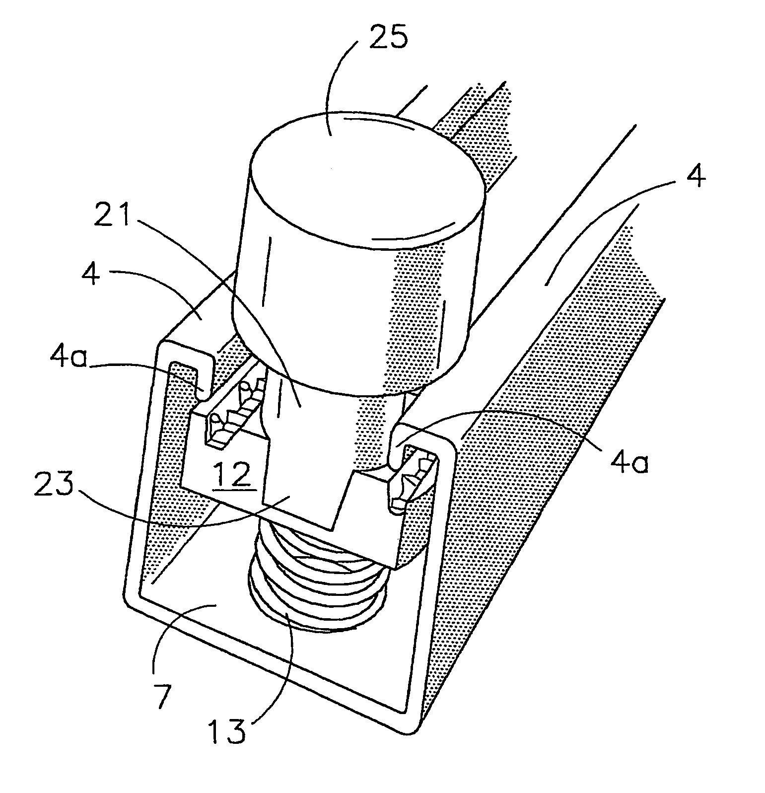
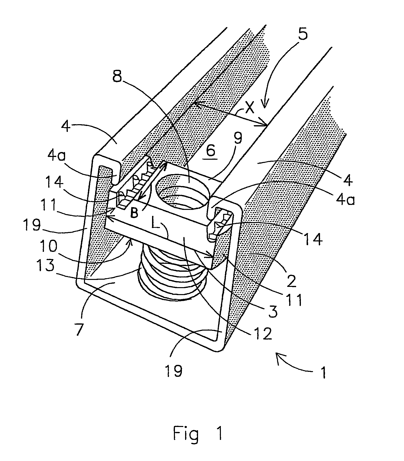
[0044]The profiled-section element 2 has a top side 5 which is provided with two flanges 4 with inwardly bent flange edges 4a which delimit a longitudinal slot 6. The profiled-section element 2 also has a base 7 lying opposite the top side 5. The flanges 4 and the base 7 are connected by side walls 19.

[0045]The nut body 3 is provided with a bore 8 which is provided with a screw thread. The nut body 3 is of a width B which is less than the width X of the longitudinal slot 6 of the profiled-section element 2. The nut body 3 is of a length L which is greater than the width X of the longitudinal slot 6 in the profiled-section element 2. The nut body 3 has a substantially planar top side 9 and a substantially planar underside 10 and, surrounding it, two short sides 11 and two long sides 12. The nut body 3 is preferably made from a metal strip. The nut body 3 is provided, at the underside 10, with a coil spring 13 which presses the nut body 3 upwards towards the flanges 4. It is also poss...


PUM


Abstract

An assembly tool (20) for a securing system. (1) The securing system comprises an elongate profiled-section element (2) having a longitudinal slot (6), which is delimited by two flanges, and an elongate nut body (3). The nut body is of a width which is less than the width of the longitudinal slot and a length (1) which is greater than the width of the longitudinal slot. The nut body is provided with a bore (8) and, on an underside, with a downwardly projecting spring (13).

Description

BACKGROUND OF THE INVENTION[0001]1. Technical Field of the Invention[0002]The invention relates to an assembly tool for a securing system comprising:[0003]an elongate profiled-section element having a top side which is provided with two flanges which delimit a longitudinal slot, and which profiled-section element also has a base lying opposite the top side,[0004]an elongate nut body of a width which is less than the width of the longitudinal slot in the profiled-section element and a length which is greater than the width of the longitudinal slot in the profiled-section element, which nut body also has a top side, an underside and, surrounding it, two short sides and two long sides, the nut body also being provided with a bore and on the underside being provided with a downwardly projecting spring.[0005]During assembly, the longitudinal axis of the nut body is brought into line with the longitudinal slot, and the nut body is introduced into the profiled-section element between the f...

Claims


Application Information

Patent Timeline
IPC IPC(8): B25B23/10F16B39/00F16B27/00B25B13/02F16B37/04
CPCB25B13/02F16B37/046
Inventor VAN WALRAVEN, JAN
Owner J VAN WALRAVEN
Why Eureka
Try Eureka