Display device, and controller

a display device and controller technology, applied in the field of display devices, can solve the problems of visual recognition of rewriting, image disturbance, and display image disturbance, and achieve the effect of improving convenience for users and improving image quality

Active Publication Date: 2011-08-04
E INK CORPORATION
View PDF5 Cites 7 Cited by
  • Summary
  • Abstract
  • Description
  • Claims
  • Application Information

AI Technical Summary

Benefits of technology

[0008]An advantage of some aspects of the invention is to provide a display device which can appropriately perform a refresh operation, improve image quality, and improve convenience for a user.

Problems solved by technology

This causes a risk that a display image is disturbed.
However, in International Publication No. 2001 / 091096, a trouble that an image disturbed due to partial rewriting is visually recognized by a user who uses an electronic book or the like for a relatively long period of time until a predetermined period of time passes is caused.
Further, a following trouble is also caused.
Therefore, a cancellation screen with the entire black or white display is visually recognized by a user frequently and thus user's convenience is impaired.
In addition, there arises a problem that partial rewriting is delayed because of the reset-driving.
There is a risk that image disturbance is accumulated and becomes significant on pixels located in a partial region on which partial rewriting is repeatedly performed and the number of times of partial rewritings is relatively large among the plurality of partial regions.

Method used


Image

  • Display device, and controller
  • Display device, and controller
  • Display device, and controller

Examples


first embodiment

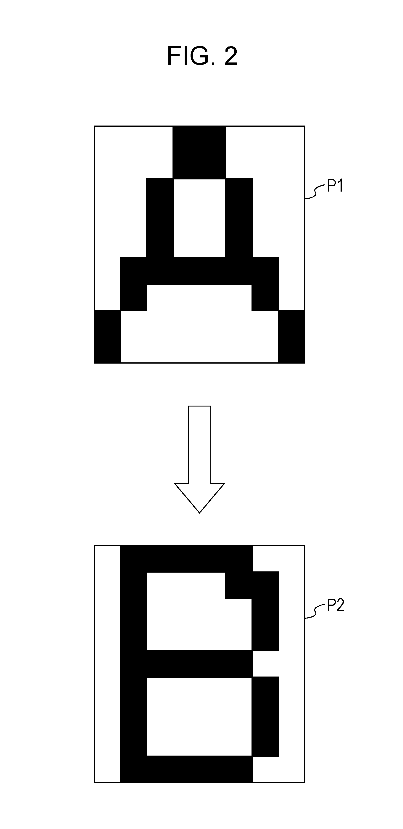
[0044]At first, a first embodiment is described with reference to FIG. 2 through FIG. 4. FIG. 2 is a view simply illustrating an example of an image before changed and an image after changed when a part of an image displayed on a display unit is changed.

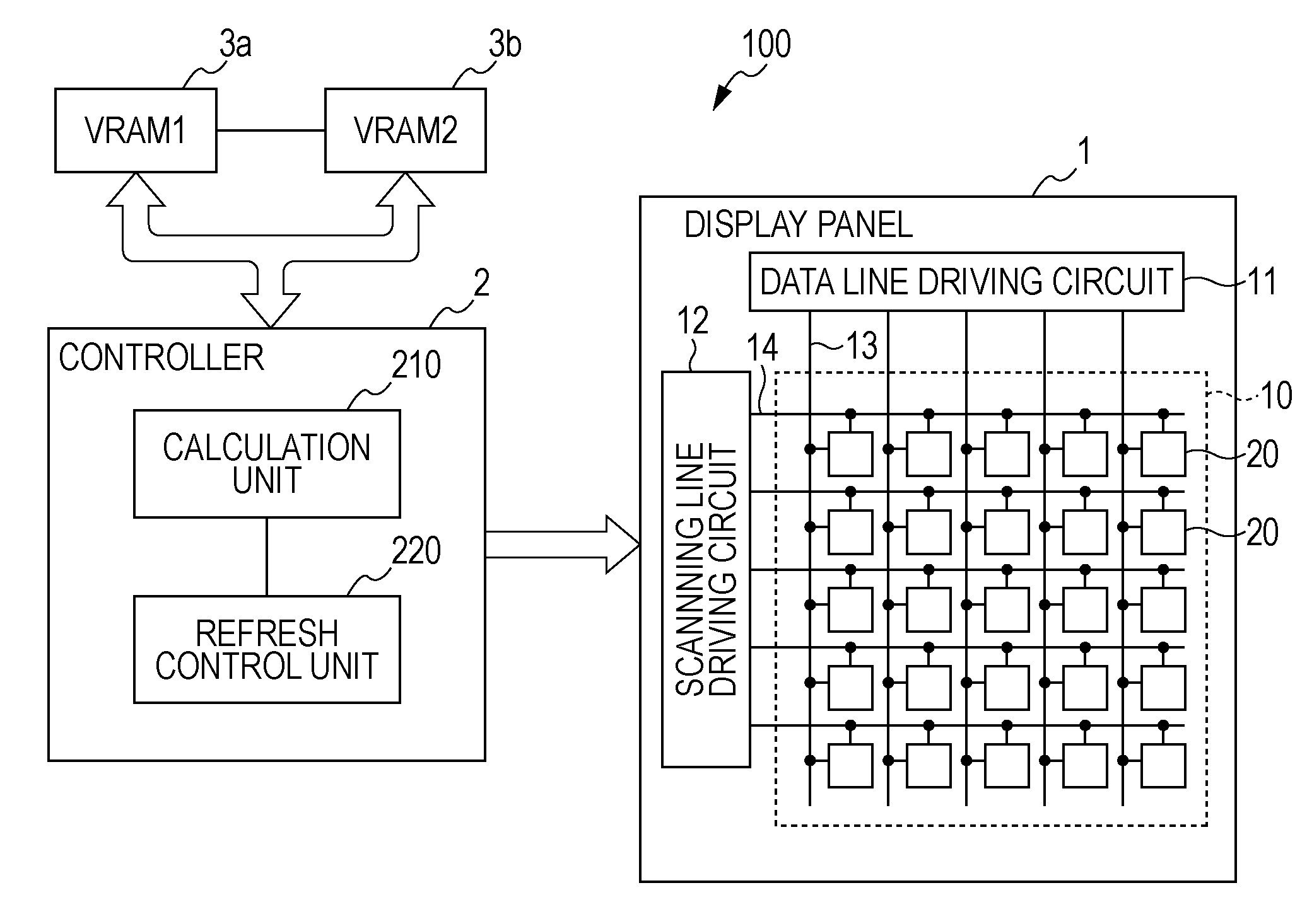
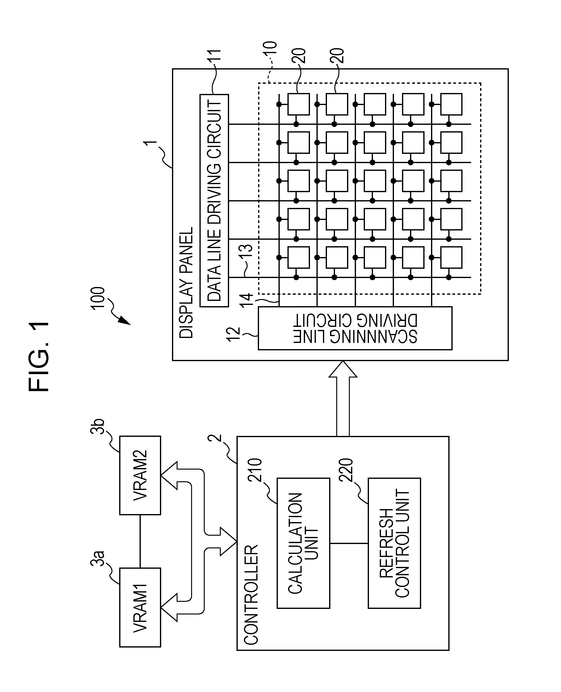
[0045]In FIG. 2, in the embodiment, a part of an image P1 displayed on the display unit 10 as illustrated in FIG. 1 is changed and the image P1 is rewritten to an image P2 after changed. In the image P1, a black character “A” is drawn on white background. In the image P2, a black character “B” is drawn on white background.

[0046]FIG. 3 is a flowchart for explaining a series of processing performed in the display device according to the embodiment.

[0047]In FIG. 3, the controller 2 accesses to the VRAM 23b and copies information indicating a display content of the image P1 before changed, which is being displayed on the display unit 10 (step S101). Subsequently, the controller 2 accesses to the VRAM 13a and rewrites the information in t...

second embodiment

[0061]Next, a second embodiment is described with reference to FIG. 5 and FIG. 6. In the second embodiment, a series of processing to the refresh operation at the time of the partial rewriting are partially different from those in the first embodiment. Hereinafter, only contents which are different from the first embodiment are described and overlapped description for the same contents as the first embodiment is not repeated in some cases.

[0062]FIG. 5 is a schematic view for explaining a plurality of partial regions formed by dividing a display unit. FIG. 6 is a flowchart for explaining a series of processing performed in a display device according to the second embodiment.

[0063]In the second embodiment, in FIG. 5, the display unit 10 is divided into a plurality of partial regions Rp and the image P1 before changed is rewritten to the image P2 after changed in the same manner as illustrated in FIG. 2. Each of the image P1 before changed and the image P2 after changed is formed with ...

third embodiment

[0072]Next, a third embodiment is described with reference to FIG. 7. In the third embodiment, a series of processing to the refresh operation at the time of the partial rewriting are partially different from those in the second embodiment. Hereinafter, only contents which are different from those in the first and second embodiments are described and overlapped description for the same contents as the first and second embodiments is not repeated in some case.

[0073]In the third embodiment, as illustrated in FIG. 5, the display unit 10 is divided into a plurality of partial regions Rp and the image P1 before changed is rewritten to the image P2 after changed as in the second embodiment.

[0074]FIG. 7 is a flowchart for explaining a series of processing performed in a display device according to a third embodiment. Hereinafter, only processing which is different from those in the first and second embodiments are described in detail with reference to FIG. 7, the same reference numerals de...


PUM


Abstract

A display device including a display unit having a plurality of pixels includes a calculation unit which accumulates the number of pixels of which display state is changed among the plurality of pixels so as to calculate the accumulated number of update pixels when a part of an image displayed on the display unit is changed, and a refresh control unit which executes a refresh operation of the display unit when the calculated accumulated number of update pixels becomes equal to or more than a defined value.

Description

BACKGROUND[0001]1. Technical Field[0002]The present invention relates to a display device such as an electrophoretic display device, for example.[0003]2. Related Art[0004]As a display device of this type, electrophoretic display devices used for electronic books or the like are disclosed in JP-A-2005-25163 and International Publication No. 2001 / 091096, for example. In JP-A-2005-25163, an image input by hand (by a pen) is overwritten onto a normal image (an image input by other than a pen) so that a display image is rewritten. To be more specific, when a normal image is displayed, after entire white display is performed by reset-driving, an image is written by writing-driving. On the other hand, when an image is input by hand, only writing-driving is performed without reset-driving. In the latter case, partial writing is performed on pixels included in a pen input region such that the pixels display a darkest state (black) (for example, second embodiment).[0005]If such partial rewrit...

Claims


Application Information

Patent Timeline
Patent Type & Authority Applications(United States)
IPC IPC(8): G09G5/00
CPCG09G3/344G09G5/00G09G2320/103G09G3/20G09G2320/0247G09G2310/04
Inventor YAMADA, YUSUKE
Owner E INK CORPORATION
Why Eureka
Try Eureka