Focusing mount

a technology of focusing mount and lens, which is applied in the direction of camera focusing arrangement, printers, instruments, etc., can solve the problems of affecting the quality of the focus, degrading the focus quality, and not being able to move the image capturing sensor in concert with any tilt or shift of the lens

Inactive Publication Date: 2011-08-04
LOREO ASIA
View PDF14 Cites 9 Cited by
  • Summary
  • Abstract
  • Description
  • Claims
  • Application Information

AI Technical Summary

Benefits of technology

[0026]An object of the invention is to provide a focusing system for lenses wherein a focusing frame is moved relative to a constraining frame whi

Problems solved by technology

For conventional devices, it is not practical to move the image capturing sensor in concert with any tilt or shift of the lens.
Any uncontrolled shifting or tilting will degrade the quality of the focus.
Even a small tilt in the orientation of the lens will result in an image becoming blurred even when the lens has been moved to its correct point of focus on the optical axis.
It is unnecessary and difficult to manufacture rigid concentric tubes of sufficient precision to slide in and out of each other with full contact.
This inevitably leads to the problems with a concentric tube system jamming when the ratio of the len

Method used


Image

  • Focusing mount
  • Focusing mount
  • Focusing mount

Examples


Embodiment Construction

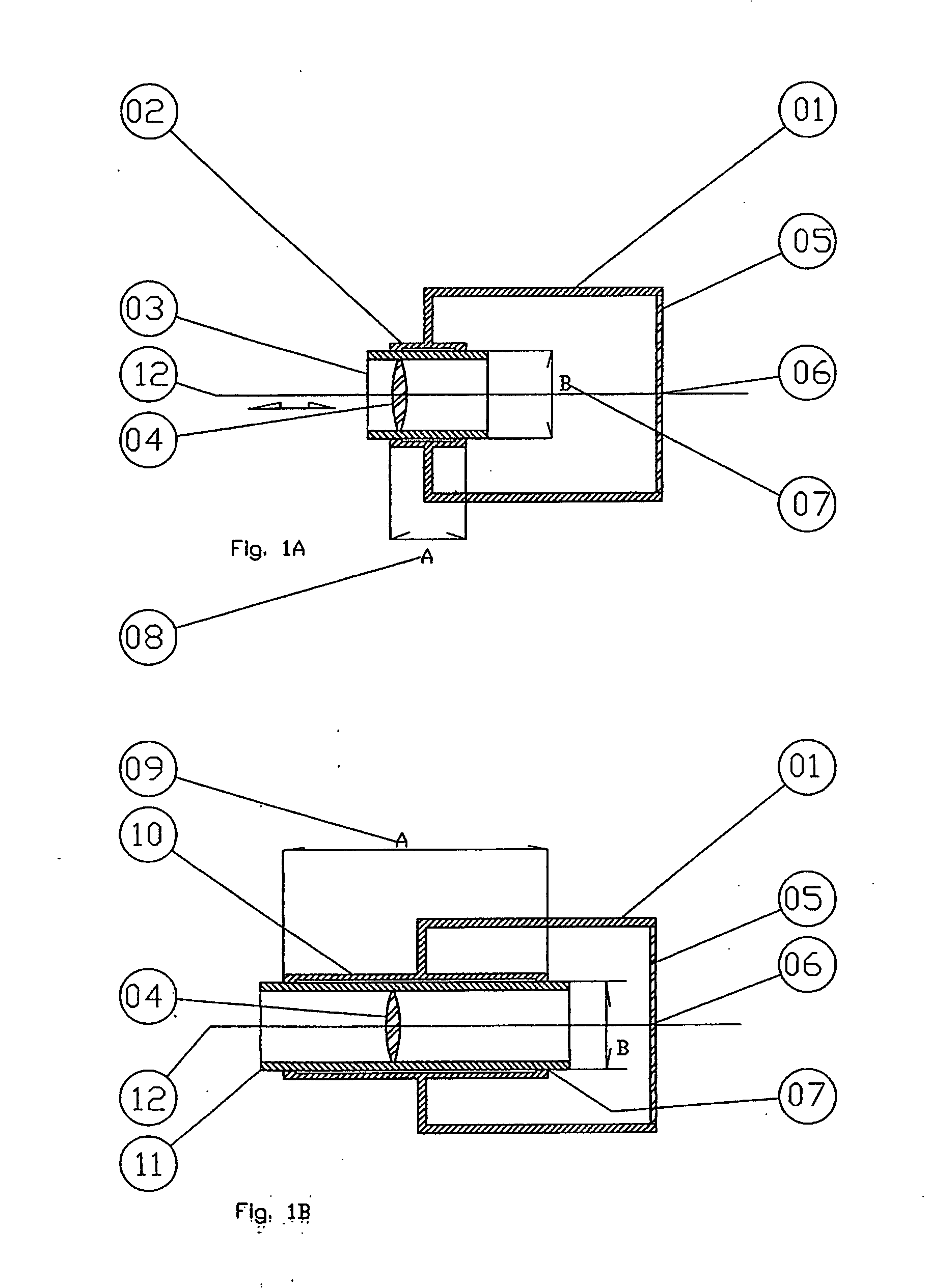
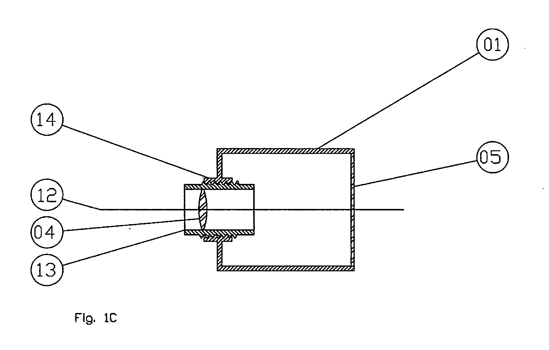
[0043]FIGS. 3A, 3B and 3C depict the invention in its most basic form.

[0044]In the concentric tube method, the outer tube is the constraining frame. It is fixed to the housing, and thereby provides support and rigidity to the focusing frame, which holds and constrains the motion of the lens along the required optical axis.

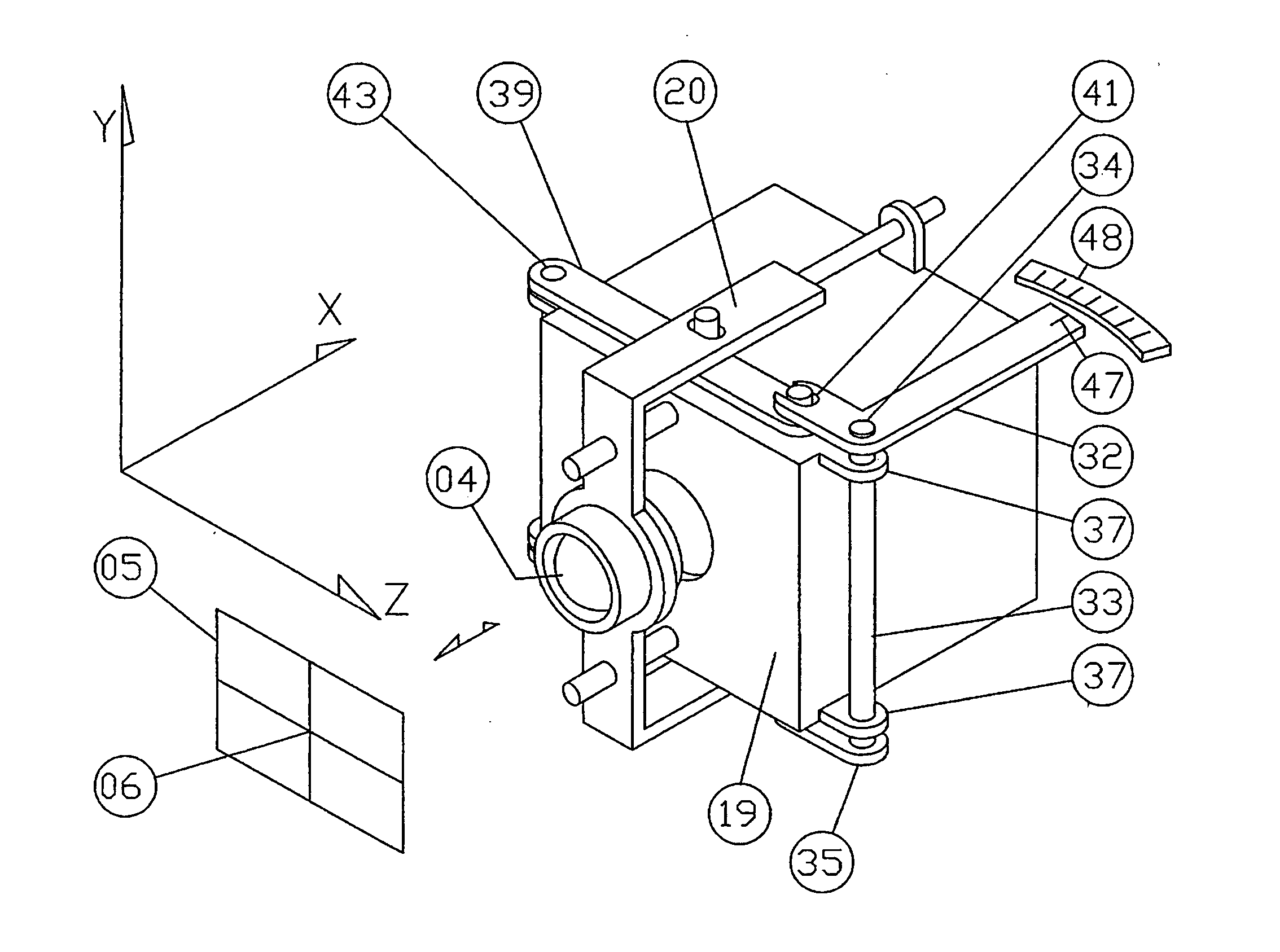
[0045]In FIGS. 3A, 3B and 3C, a constraining frame 19 is still part of a fixed housing. In fact, the entire housing functions as the constraining frame. This provides support and rigidity and constrains the motion of the lens 04 along the optical axis 12. However, this constraining frame 19 no longer supports and guides a long, thin inner focusing frame. Instead, the focusing frame is only represented by means of four focusing rails 20. (As used herein, the term “focusing rail” mans a part fixed to the focusing frame, and the term “constraining rail” means a part fixed to the constraining frame.) Each focusing rail 20 has two freely sliding hole and pin joints 21. ...


PUM


Abstract

A focusing mount includes a focusing frame fixed to a focus tube with at least one lens having an optical axis which is connected to a constraining frame by prismatic joints for enabling movement of the focusing mount along the optical axis without any twisting, lateral, rotational or swing movements.

Description

BACKGROUND OF THE INVENTION[0001]1. Field of the Invention[0002]This invention relates to an improved lens mounting system which provides all the benefits of a simple sliding tube but without the associated drawbacks, and more particularly to a focusing mechanism which moves a focusing frame along the optical axis of each lens system linearly by constraining lateral, rotational and swing movements.[0003]2. Description of the Prior Art[0004]There are many ways to focus a lens. This invention concerns the focusing of a lens by means of mechanically changing its position along a fixed path, which maintains the orientation of the lens and follows the optical axis of the lens. This movement may be achieved by manual operation, or it can be motorized. This invention does not cover methods which involve using electronic or other means to change the shape or optical properties of a lens to achieve change in focus.[0005]In an imaging device, when a lens is moved along its central optical axi...

Claims


Application Information

Patent Timeline
IPC IPC(8): G02B7/04
CPCG02B7/04G02B7/023G02B7/10G02B7/08G03B3/02
Inventor LO, TAK SAU ANTHONY
Owner LOREO ASIA
Why Eureka
Try Eureka