Light emitting device, illuminating device, and vehicle headlight

Active Publication Date: 2011-08-11
SHARP FUKUYAMA LASER CO LTD
View PDF100 Cites 80 Cited by
  • Summary
  • Abstract
  • Description
  • Claims
  • Application Information

AI Technical Summary

Benefits of technology

[0036]As described above, the light emitting device of the present invention includes: an excitation light source which generates excitation light; a light emitting section from which light is emitted in response to the excitation light; and a light guide irradiation member, having one end and the other end, which (i) guides the excitation light, entered via the one end, toward the other end and (ii) irradiates a predetermined light irradiation area of the light emitting section wit

Problems solved by technology

However, rays of light emitted from an emission edge of the bundle fiber are converged with the use of a convex lens, and there

Method used


Image

  • Light emitting device, illuminating device, and vehicle headlight
  • Light emitting device, illuminating device, and vehicle headlight
  • Light emitting device, illuminating device, and vehicle headlight

Examples


Embodiment Construction

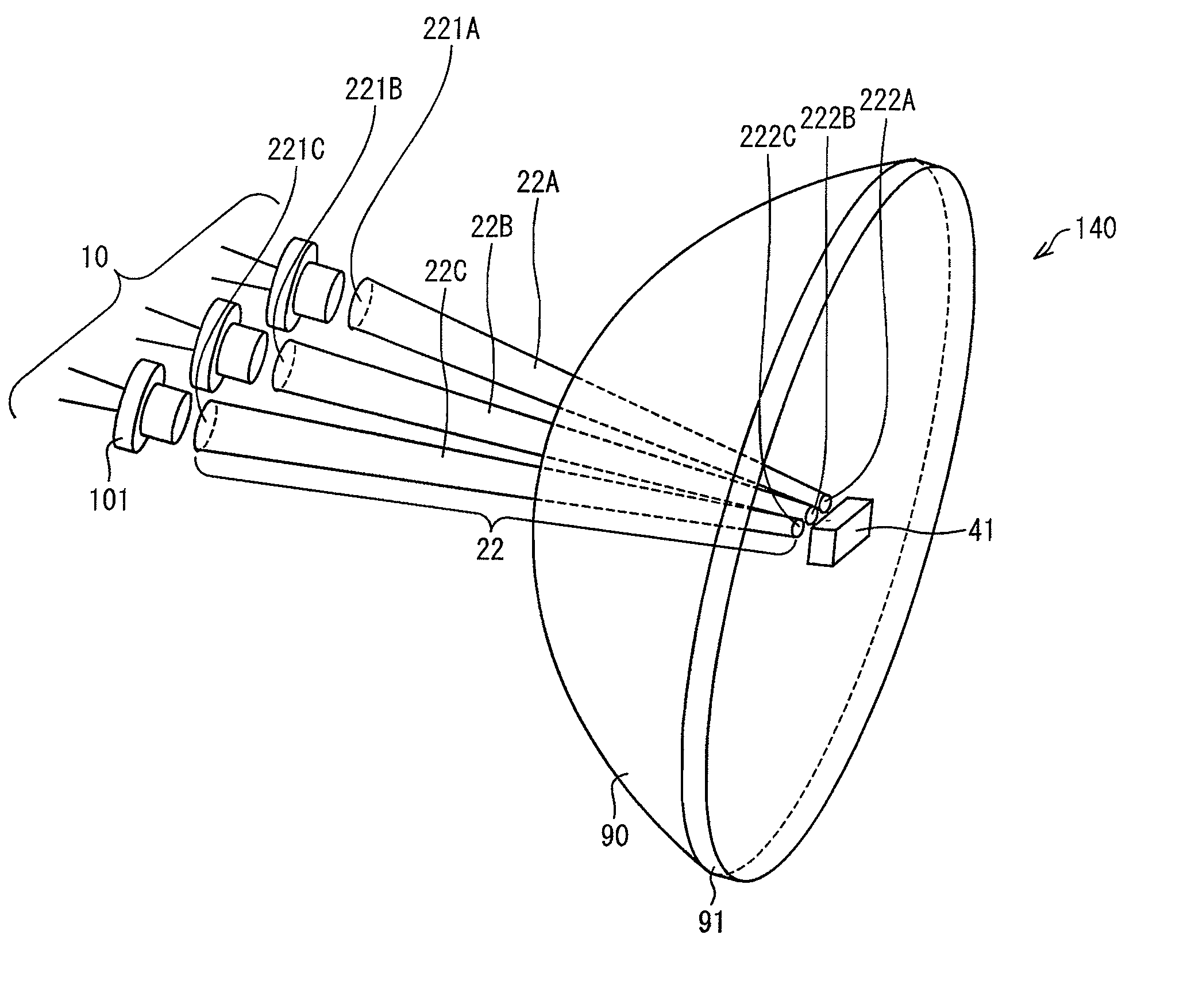
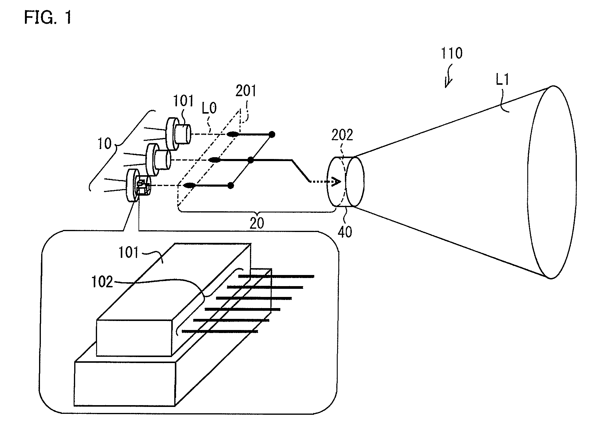
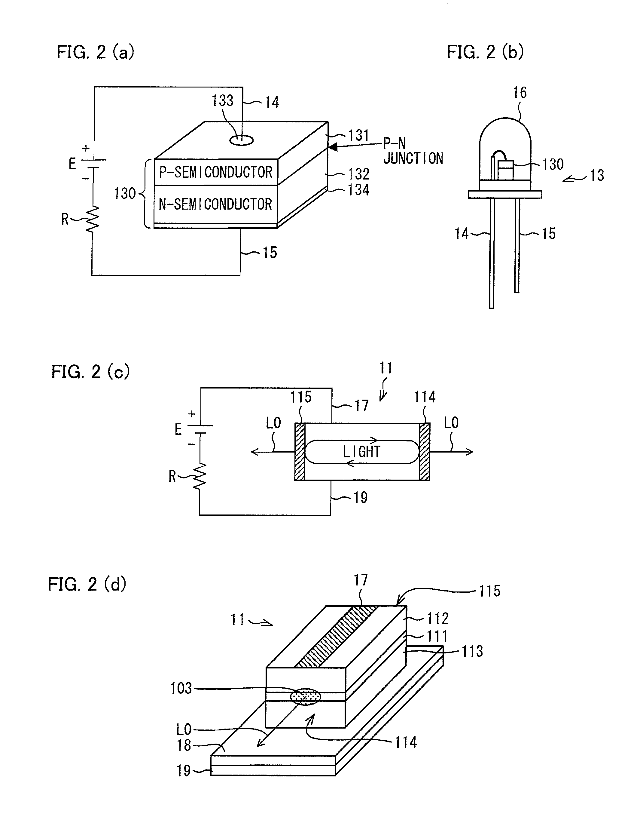
[0062]The following describes an embodiment of the present invention with reference to FIG. 1 through FIG. 9(c). As to configurations which are not described in a section below, descriptions of such configurations are sometimes omitted as appropriate. Note, however, that such configurations are identical to those described in the other sections. For convenience, the same reference numerals are given to members having functions identical to those described in the other sections, and descriptions of the members are omitted as appropriate.

[0063]Note that each of a light emitting device (illuminating device, vehicle headlight) 110, a light emitting device (illuminating device, vehicle headlight) 120A, a light emitting device (illuminating device, vehicle headlight) 120B, and an illuminating device (light emitting device, vehicle headlight) 140 is described as a light emitting device part of an illuminating device or a vehicle headlight. However, embodiments of the present invention are ...


PUM


Abstract

A light emitting device of the present invention includes: a laser diode group which generates a plurality of laser beams; a cylindrical light emitting element which emits incoherent light in response to the plurality of laser beams; and a light guide irradiation section which (i) guides the plurality of laser beams entered via a light incidence plane toward a light irradiation plane and (ii) irradiates the light irradiation area of the cylindrical light emitting element with the plurality of laser beams thus guided. The light irradiation plane of the light guide irradiation section has an area which is smaller than that of the light incidence plane.

Description

[0001]This Nonprovisional application claims priority under 35 U.S.C. §119(a) on Patent Application No. 2010-028176 filed in Japan on Feb. 10, 2010, the entire contents of which are hereby incorporated by reference.TECHNICAL FIELD [0002]The present invention relates to (i) a light emitting device and an illuminating device each of which includes an excitation light source and a light emitting section containing a fluorescent substance and (ii) a vehicle headlight including the light emitting device or the illuminating device.BACKGROUND ART [0003]In these years, diligent studies have been carried out on a light emitting device in which a semiconductor light emitting element (solid-state light source) such as a light emitting diode (LED) or a laser diode (LD) is used as an excitation light source.[0004]As an example of such a conventional light emitting device, Patent Literature 1 discloses a technique in which a single optical fiber is used.[0005]According to the technique disclosed ...

Claims


Application Information

Patent Timeline
IPC IPC(8): B60Q1/04F21V8/00
CPCF21S48/1154G02B6/0008F21S48/1241F21S41/143F21S41/24F21S41/16F21S41/151F21S41/176
Inventor KISHIMOTO, KATSUHIKOTAKAHASHI, KOJIITO, SHIGETOSHIKAWANISHI, HIDENORI
Owner SHARP FUKUYAMA LASER CO LTD
Why Eureka
Try Eureka