Commissioning lighting systems

a lighting system and lighting technology, applied in the field of lighting systems, can solve the problems of inability to use combinations, inability to meet the needs of lighting users, etc., and achieve the effect of facilitating wide-spread adoption of sophisticated control systems

Active Publication Date: 2011-08-18
WTEC GMBH
View PDF83 Cites 214 Cited by
  • Summary
  • Abstract
  • Description
  • Claims
  • Application Information

AI Technical Summary

Benefits of technology

[0014]A method of commissioning a lighting system is disclosed. A user can be provided with a pointing device capable of emitting or returning a signal which can be received by detectors co-located with each fixture in the lighting system. The user can add a fixture to a group by aiming the pointing device at the fixture when the fixture is not assigned to the group, and the user can remove a fixture from a group in the same way when the fixture was previously assigned to the group. This commissioning method can be used with a lighting system comprising a central control unit and a plurality of fixtures comprising luminaires, optional control devices, and optional standalone sensors, where each fixture includes a co-located sensor capable of receiving the signal emitted by the pointing device, and a central control unit which can communicate with each fixture. Additional user gestures are disclosed together with methods for the central control unit to acknowledge gestures. Additional communications methods among components of the lighting system are also disclosed. Further objects and advantages of the present invention will be apparent from the following description, reference being made to the accompanying drawings.

Problems solved by technology

Such systems can range in complexity from a single wall switch and bulb to commercial building lighting systems comprising hundreds of luminaires, sensors, and control devices.
However, such combinations may not be used, and each component is separately purchased, installed, and wired together in order to create functional groups.
The cost of discrete components as well as the cost of installation and programming labor may have inhibited wide-spread adoption of sophisticated control systems.

Method used


Image

  • Commissioning lighting systems
  • Commissioning lighting systems
  • Commissioning lighting systems

Examples


Embodiment Construction

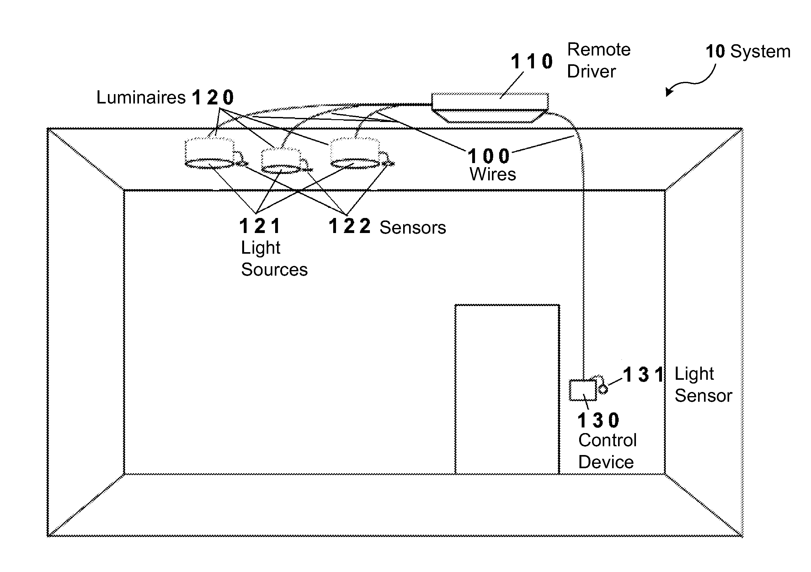
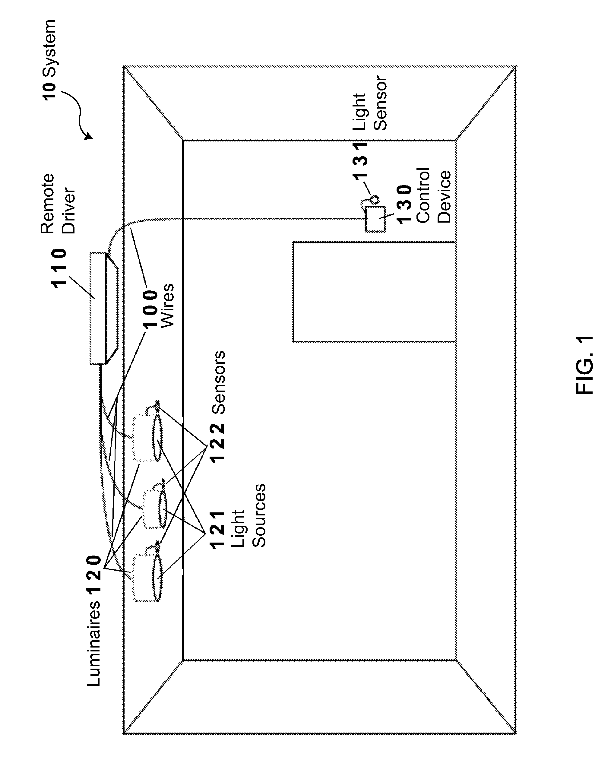
[0020]Before the present invention is described in detail, it is to be understood that unless otherwise indicated this invention is not limited to specific construction materials, electronic components, or the like, as such may vary. It is also to be understood that the terminology used herein is for the purpose of describing particular embodiments only and is not intended to limit the scope of the present invention.

[0021]As used herein and in the claims, the singular forms “a,”“an” and “the” may include plural referents unless the context clearly dictates otherwise. Thus, for example, reference to “a fixture” may include one or more fixtures; reference to “a sensor” may include one or more sensors, and so forth.

[0022]Where a range of values is provided, it is understood that each intervening value, to the tenth of the unit of the lower limit unless the context clearly dictates otherwise, between the upper and lower limit of that range, and any other stated or intervening value in t...


PUM


Abstract

Commissioning a lighting system is disclosed. A user can be provided with a pointing device capable of emitting or returning a signal which can be received by detectors co-located with each fixture in the lighting system. The user can add a fixture to a group by aiming the pointing device at the fixture when the fixture is not assigned to the group, and the user can remove a fixture from a group in the same way when the fixture was previously assigned to the group. Additional user gestures are also disclosed.

Description

[0001]This application is a continuation-in-part application of, and claims priority under 35 U.S.C. §120 to, U.S. patent application Ser. No. 12 / 708,460, “METHODS OF COMMISSIONING LIGHTING SYSTEMS” filed Feb. 18, 2010, the entire contents of which are incorporated by reference.BACKGROUND[0002]1. Technical Field[0003]One or more embodiments of the present invention relate to lighting systems and functional groups of fixtures in a lighting system.[0004]2. Related Art[0005]Lighting systems for areal illumination may comprise (1) a set of “luminaires” (light fixtures comprising mounting hardware and one or more light-emitting components, such as incandescent or fluorescent bulbs or arrays of light-emitting diodes [LEDs]), together with (2) one or more sensor components (motion sensors, light sensors, and the like), (3) control devices (such as dimmers and switches), and (4) power drivers to set the output light level of each luminaire as a function of sensor outputs and control device ...

Claims


Application Information

Patent Timeline
Patent Type & Authority Applications(United States)
IPC IPC(8): H05B37/02
CPCH05B37/0218Y02B20/46H05B37/0272H05B37/0227H05B47/175H05B47/11H05B47/105Y02B20/40H05B47/115H05B47/195
Inventor HENIG, ROBERTFOWLER, DAVIDNULU, DEEPAKLEONARD, DAVIDZWANZIG, CARL P.
Owner WTEC GMBH
Why Eureka
Try Eureka