High Efficiency Roller Shade

a high-efficiency, roller shade technology, applied in the direction of dynamo-electric converter control, shutter/movable grille, door/window protection device, etc., can solve the problems of high self-generated noise, inadequate battery life, and battery-powered systems

Active Publication Date: 2011-08-25
THE WATT STOPPER
View PDF95 Cites 74 Cited by
  • Summary
  • Abstract
  • Description
  • Claims
  • Application Information

AI Technical Summary

Benefits of technology

This patent describes an improved version of a motorized roller shade system which has several technical benefits compared to older versions. It uses a special design for its motor/control mechanism that allows it to operate without causing any rotation or movement during installation. This makes it easier and more secure to install than previous designs. Additionally, this new technology also provides better performance and reliability over time compared to other systems on the market.

Problems solved by technology

The technical problem addressed in this patent text relates to improving the performance and reliability of battery-powered roller shades, which have various limitations such as short battery lives, lack of counterbalancing capabilities, and limited operational modes.

Method used


Image

  • High Efficiency Roller Shade
  • High Efficiency Roller Shade
  • High Efficiency Roller Shade

Examples


Embodiment Construction

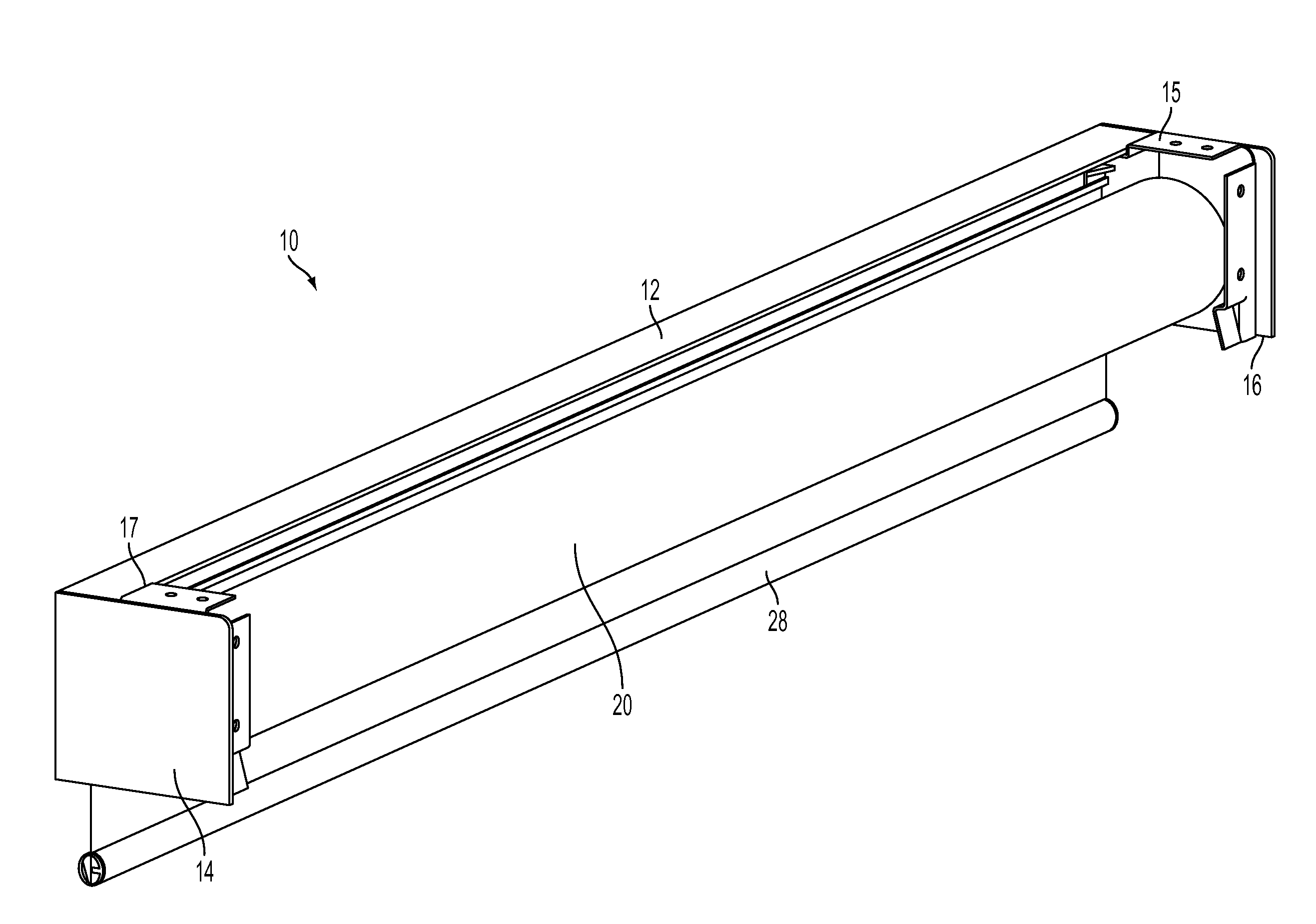
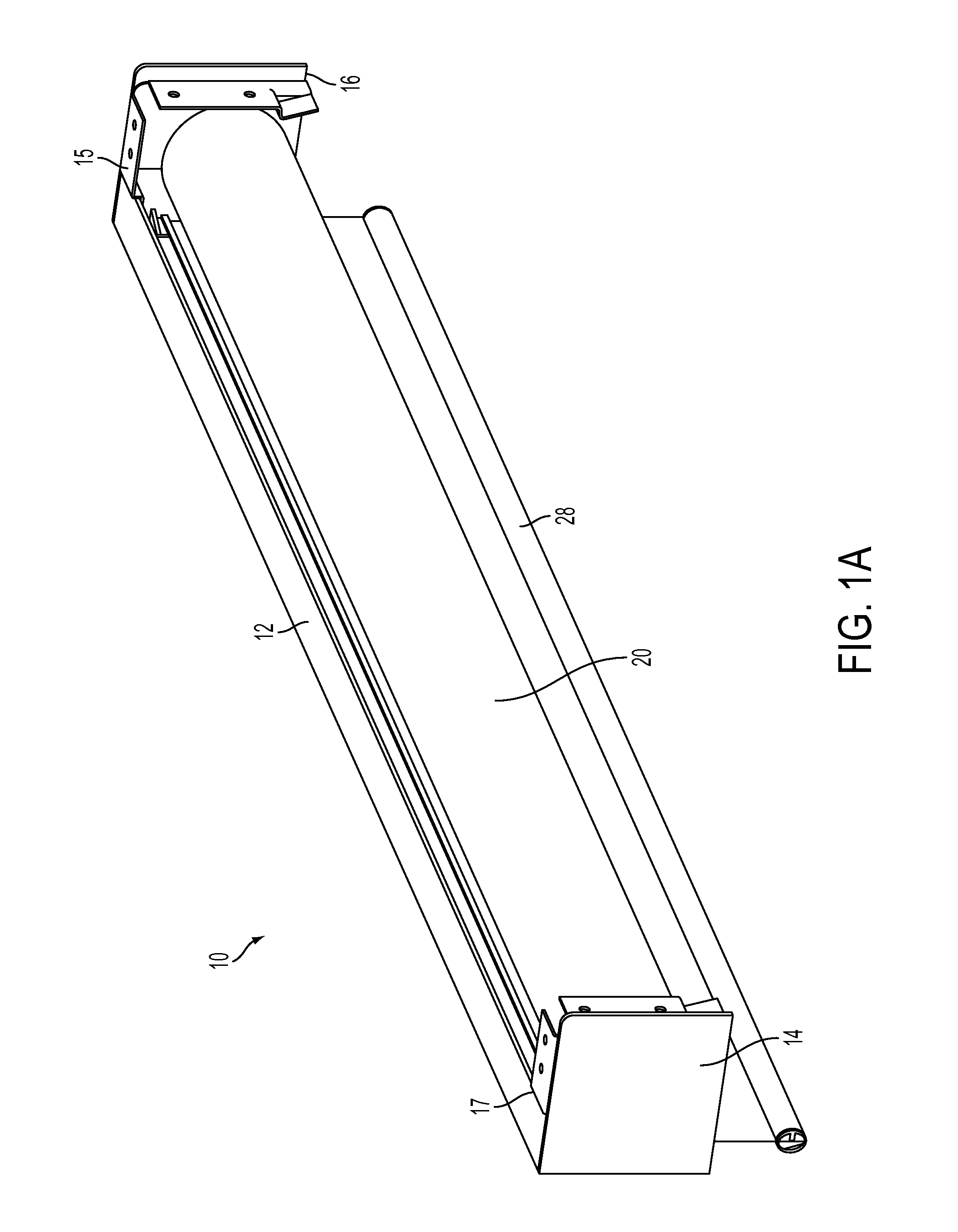
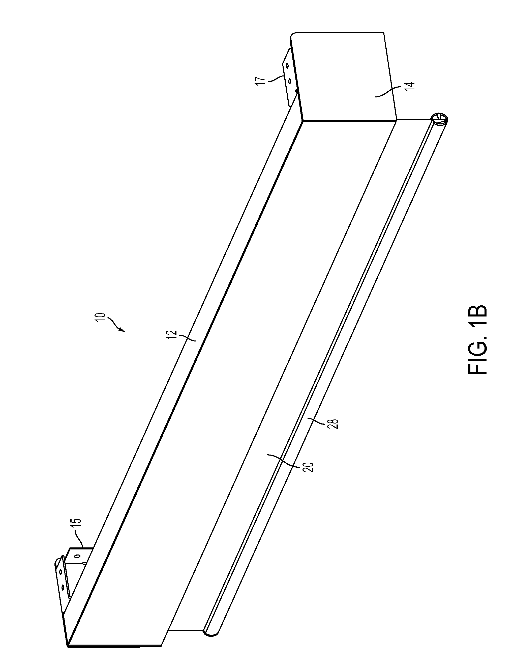
[0032]The invention will now be described with reference to the drawing figures, in which like reference numerals refer to like parts throughout. The term “shade” as used herein describes any flexible material, such as a shade, a curtain, a screen, etc., that can be deployed from, and retrieved onto, a storage tube.

[0033]Embodiments of the present invention provide a remote controlled motorized roller shade in which the batteries, DC gear motor, control circuitry are entirely contained within a shade tube that is supported by bearings. Two support shafts are attached to respective mounting brackets, and the bearings rotatably couple the shade tube to each support shaft. The output shaft of the DC gear motor is fixed to one of the support shafts, while the DC gear motor housing is mechanically coupled to the shade tube. Accordingly, operation of the DC gear motor causes the motor housing to rotate about the fixed DC gear motor output shaft, which causes the shade tube to rotate about...


PUM


Abstract

The present invention advantageously provides a motorized roller shade that includes a shade tube, a motor/controller unit and a power supply unit. The motor/controller unit is disposed within the shade tube, and includes a bearing, rotatably coupled to a support shaft, and a DC gear motor. The output shaft of the DC gear motor is coupled to the support shaft such that the output shaft and the support shaft do not rotate when the support shaft is attached to the mounting bracket.

Description


Claims


Application Information

Patent Timeline
Owner THE WATT STOPPER
Why Eureka
Try Eureka