Eureka AIR delivers breakthrough ideas for toughest innovation challenges, trusted by R&D personnel around the world.

Wound Layered Tube Heat Exchanger

Active Publication Date: 2011-09-01
MODINE GRENADA LLC
View PDF5 Cites 8 Cited by
  • Summary
  • Abstract
  • Description
  • Claims
  • Application Information

AI Technical Summary

Benefits of technology

[0021]The invention includes a wound tube heat exchanger, which receives a heat exchange fluid that flows within the exchanger. The exchanger has one or more layers of a one or more small diameter (preferably with an OD<5 mm), tubes. In one embodiment, the tube surface is bare. In other embodiments, the outside tube surface is enhanced to produce turbulence and convective heat transfer. Each layer is wound around and is separated by a spacer members. At least some of the layers have an ovate, oblong or racetrack-like configuration with a pair of opposing

Problems solved by technology

One disadvantage, however, is that fins add to material and manufacturing cost, bulk, handling, servicing and overall complexity.
Further, they occupy space and therefore reduce the number of tubes that can fit within a given cross sectional area and they collect dust and dirt and may get clogged, thereby diminishing their effectiveness.
This promotes an increase in the pressure drop of the external fluid across the heat transfer surface and may add to heat exchanger costs by requiring more pumping power.
In general, expense related to pumping is a function of the pressure drop.

Method used


Image

  • Wound Layered Tube Heat Exchanger
  • Wound Layered Tube Heat Exchanger
  • Wound Layered Tube Heat Exchanger

Examples


Embodiment Construction

)

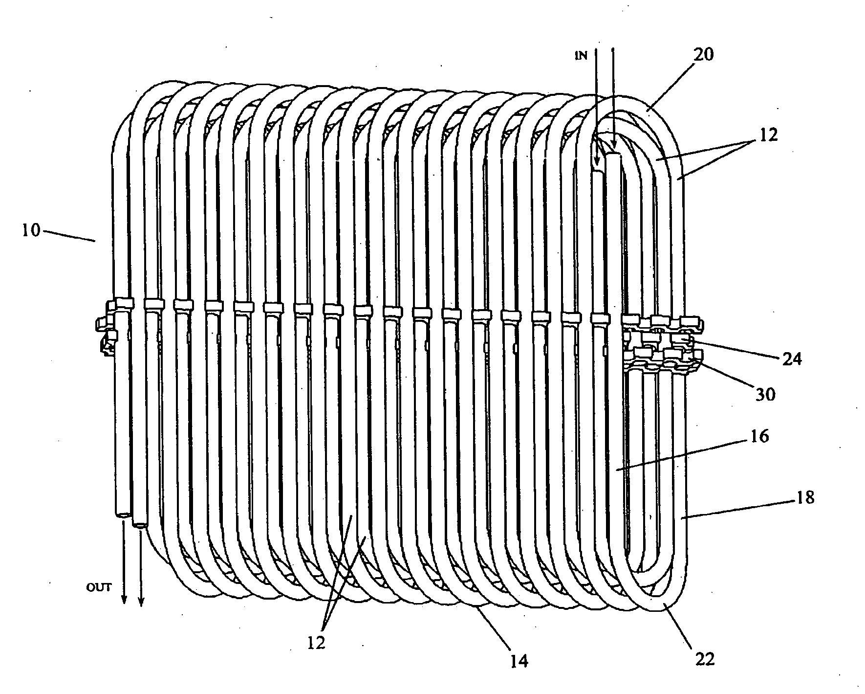
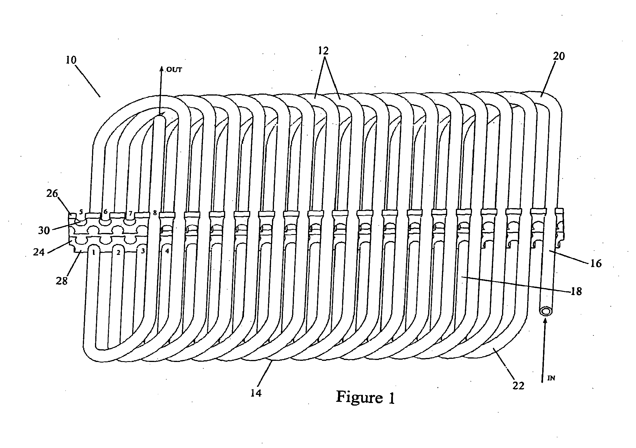
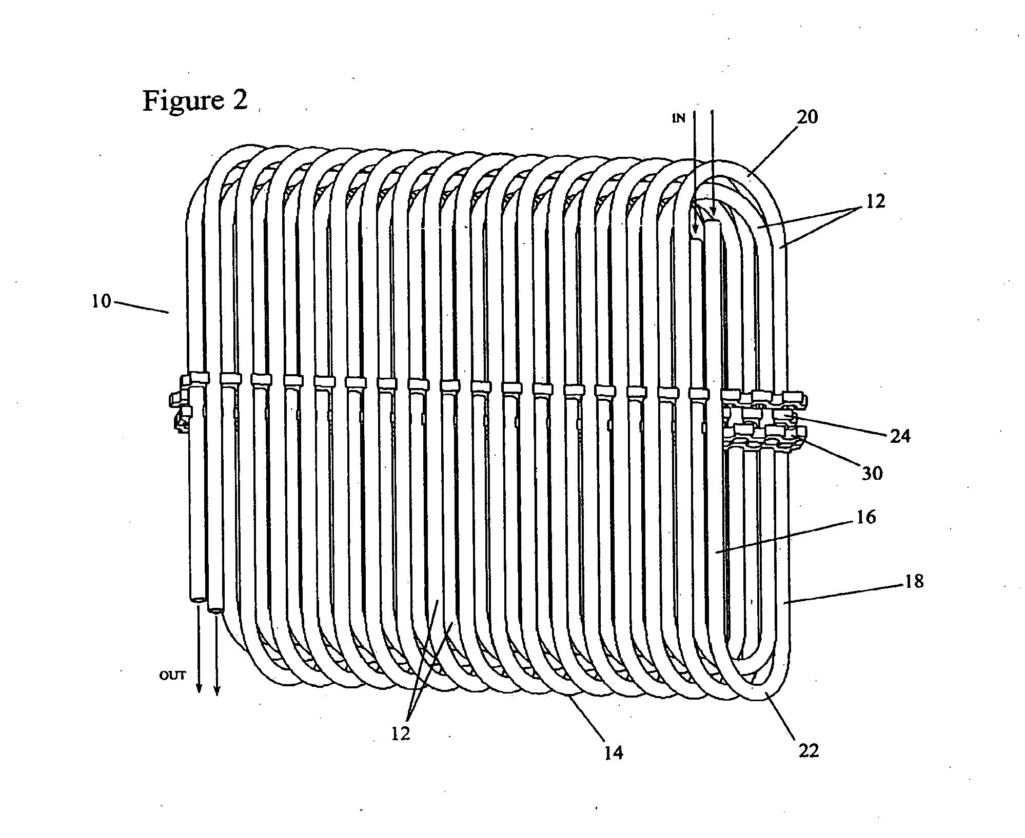
[0030]FIGS. 1&3-4 depict a tube heat exchanger 10 for receiving a heat exchange fluid that flows within the heat exchanger. In one embodiment the tube surface is bare. In other embodiments, the outside tube surface is enhanced to disturb air flow and promote convective heat transfer. The heat exchanger has one or more layers 12 of a single, long, continuous, tube 14. The tube 14 has an outside diameter (OD), an inside diameter (ID) along which the heat exchange fluid passes, and a wall thickness (T=(OD−ID) / 2)). It will be appreciated that the tube 14 need not be circular or annular in cross section. For some applications, for example, the tube 14 may usefully have an oval configuration or other non-circular cross section which may be helpful in directing incident air flow and promoting local turbulence.

[0031]At least some of the one or more layers 12 have an ovate, oblong, or racetrack-like configuration 15 (FIG. 3). Each revolution includes a pair of opposing linear runs 16,18 tha...


PUM


Abstract

A wound tube heat exchanger 10 article that receives a heat exchange fluid and its method of manufacture. The exchanger 10 has one or more layers 12 of a tube 14. In one embodiment, the tube surface is bare. In other embodiments, the outside tube surface is enhanced to produce turbulence. At least some of the layers 12 have an ovate oblong configuration. A pair of opposing linear runs 16,18 is connected by a pair of opposing curved sections 20,22. In some embodiments, the layers are circular, oval or rectangular with radiused corners. An elongate spacer member 24 has forwardly 26 and rearwardly 28 facing edges. Defined within those edges are engagement surfaces 30 that detachably retain the opposing linear runs 16,18.

Description

BACKGROUND OF THE INVENTION[0001]1. Field of the Invention[0002]This invention relates generally to tube configurations used in heat exchangers and their methods of manufacture.[0003]2. Background Art[0004]In many chemical, electronic, and mechanical systems, thermal energy is transferred from one location to another or from one fluid to another. Heat exchangers allow the transfer of heat from one fluid (liquid or gas) to another fluid. Conventionally, the reasons for transferring heat energy are:[0005](1) to heat a cooler fluid using a warmer fluid;[0006](2) to reduce the temperature of a hot fluid by using a cooler fluid;[0007](3) to boil a liquid using a hotter fluid;[0008](4) to condense a gas by a cooler fluid; or[0009](5) to boil a liquid while condensing a hotter fluid in the gaseous state.[0010]Regardless of the function the heat exchanger fulfills, in order to transfer heat, the fluids in thermal contact must be at different temperatures to allow heat to flow from the warme...

Claims


Application Information

Patent Timeline
IPC IPC(8): F28D7/02F28F1/10B23P15/26
CPCF28D7/02Y10T29/49391F28F2240/00F28F9/0132
Inventor NAUKKARINEN, OLLI PEKKA
Owner MODINE GRENADA LLC
Why Eureka
Eureka Blog
Learn More