
Pressure relief valve and vent assembly

a technology of pressure relief valves and vent assemblies, which is applied in the direction of functional valve types, liquid fuel feeders, non-fuel substance addition to fuel, etc., can solve the problems of not offering the level or degree of filtration necessary to meet modern contamination control standards, the micron rating of air filters is too coarse, and the effect of being exposed to rainfall and wash-down water

Active Publication Date: 2011-09-08
WALNAB
View PDF13 Cites 12 Cited by
  • Summary
  • Abstract
  • Description
  • Claims
  • Application Information

AI Technical Summary

Benefits of technology

[0016]Preferably the pressure relief valve is integral with the tank vent, More preferably the pressure relief valve includes one or more float elements arranged to co-operate with a reciprocating vent tube located at least in part within the fluid passageway. Even more preferably the relief valve also includes biasing means designed to urge the reciprocating vent tube into seated engagement with the vent body while still allowing fluid to vent through said tube. Still more preferably an uppermost of the float elements is arranged to block the vent tube when the tank is substantially full whereby pressurisation of the tank actuates the relief valve to unseat the vent tube from the vent body and to allow fluid to exhaust the tank via the exhaust outlet.

Problems solved by technology

However these systems do not offer the level or degree of filtration necessary to comply with modern contamination control standards, i.e. the micron rating of the air filters is too coarse.
Further, the intake ports of the filter element are directly exposed to the atmosphere, and thus exposed to rainfall and wash-down water.

Method used


Image

  • Pressure relief valve and vent assembly
  • Pressure relief valve and vent assembly
  • Pressure relief valve and vent assembly

Examples


Embodiment Construction

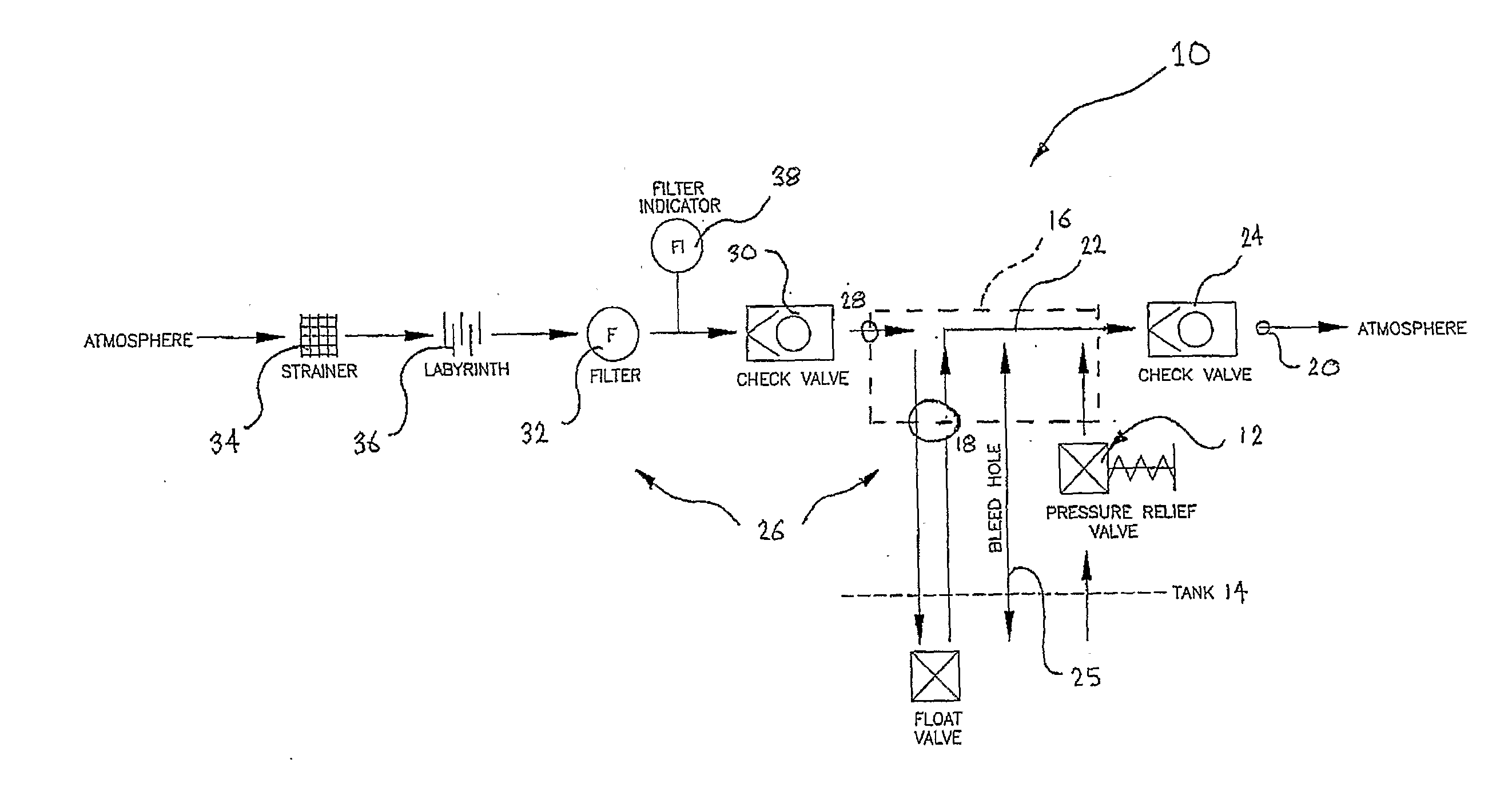
[0030]FIG. 1 is a schematic flow diagram of the fluid and ambient air flow through a pressure relief valve and vent assembly 10 of one embodiment of the present invention. The pressure relief valve and vent assembly 10 comprises:

[0031]1. A pressure relief valve 12 adapted to couple to a tank 14; and

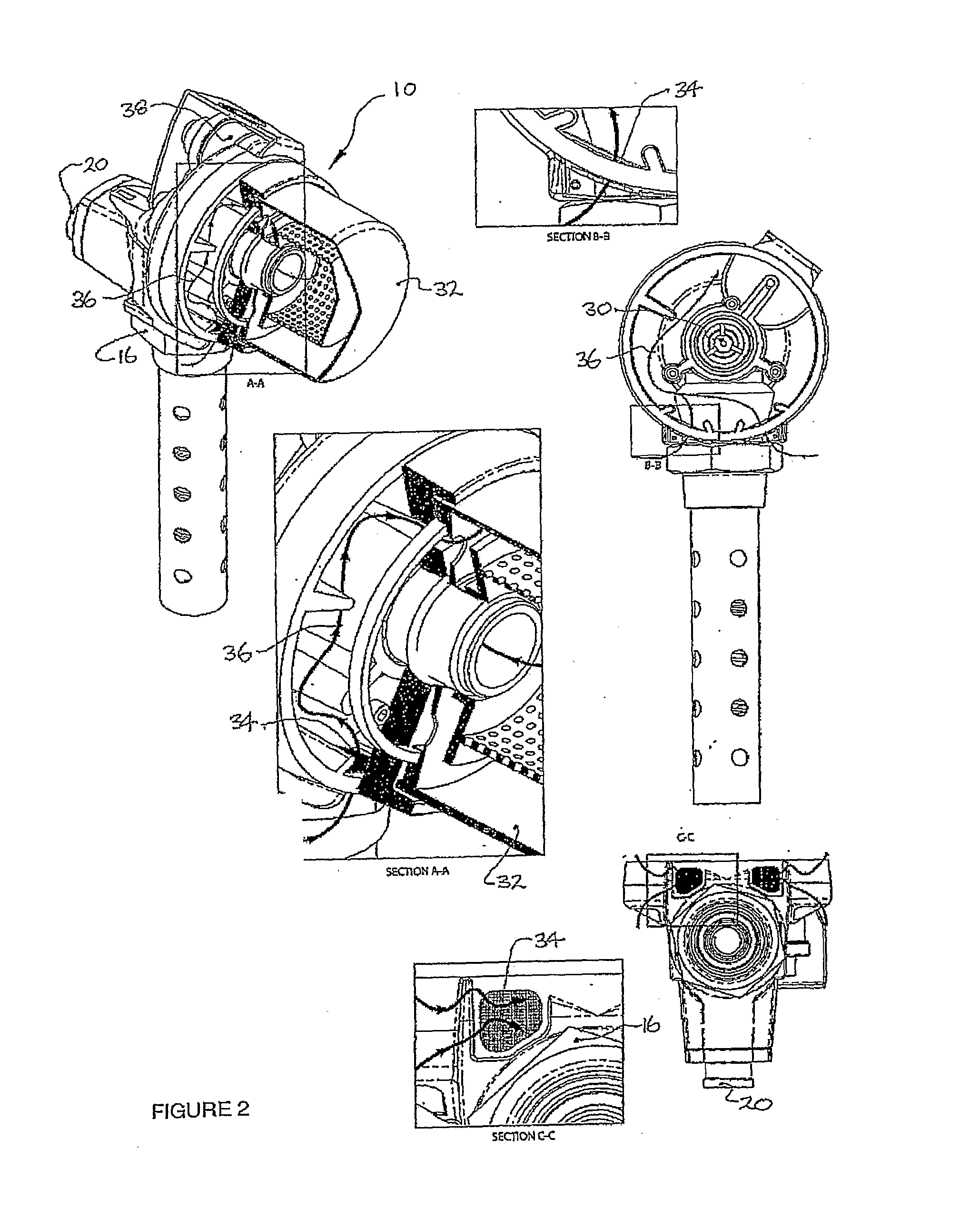
[0032]2. A tank vent designated generally as 26 comprising:[0033](a) A vent body shown schematically in hidden detail as the rectangular boxed section 16 having a vent inlet shown circled at 18 and an exhaust outlet shown circled at 20 and being in communication with each other via a fluid passageway 22;[0034](b) An exhaust check valve 24 connected to the vent body 16 at the exhaust outlet 20.

[0035]The tank vent 26 is operatively coupled to the pressure relief valve 12 and in this embodiment they are integrated to form an integrated pressure relief valve and vent assembly 10.

[0036]The exhaust check valve 24 is configured to allow fluid to flow through the fluid passageway 22 in one direct...


PUM


Abstract

The present invention relates broadly to a pressure relief valve and vent assembly (10) comprising a pressure relief valve (12) arranged to couple to a tank (14), and a tank vent (26). The tank vent (26) comprises a vent body (16) having a vent inlet (18) and a exhaust outlet (20) in communication with each other via a fluid passageway (22). The tank vent also comprises an exhaust check valve (24) connected to the vent body (16) at the exhaust outlet (20). The exhaust check valve (24) is arranged to allow fluid to flow through the fluid passageway (22) in one direction only from the tank (14) to atmosphere via the vent inlet (18) and the exhaust outlet (20). the pressure relief valve and vent assembly (10) also includes an ambient air inlet (28) in fluid communication with the fluid passageway (22). The ambient air inlet (28) is arranged to permit the flow of ambient air from atmosphere into the tank (14) via the vent inlet (18). The tank vent (26) also comprises an ambient air inlet check valve (30) configured to allow air flow in one direction only from atmosphere to the tank (14) via the air inlet (28).

Description

FIELD OF THE INVENTION[0001]The present invention relates broadly to a pressure relief valve and vent assembly and relates particularly, although not exclusively, to a tank vent.BACKGROUND OF THE INVENTION[0002]The industry standard method of refuelling large diesel powered equipment in the mining, railway, and earthmoving industries has incorporated dry-break fluid couplings designed to transfer diesel fuel from a dispensing point into the fuel tank onboard the equipment. An integral component of this system is the specialised vent fitted to the tank being refuelled. This vent fulfils a number of key roles, including:[0003]Free discharge of air from the tank during the refuelling process, at fuel levels under the level at which the vent valve is closed.[0004]Closure of the main vent passage once the fuel level within the tank reaches a certain level on the vent. This essentially seals the tank allowing it to be pressurised as fuel continues to enter the tank.[0005]Free-to-air passa...

Claims


Application Information

Patent Timeline
Patent Type & Authority Applications(United States)
IPC IPC(8): F16K24/04
CPCB60K15/03519F02M25/0872F16K24/06F16K15/063F16K24/04F02M37/0076Y10T137/7779Y10T137/7837Y10T137/8634
Inventor GRILLMEIER, DAVIDJEFFRESS, JOSHUAPEATTIE, ADAM
Owner WALNAB
Learn More