Apparatus for providing touch feedback for user input to a touch sensitive surface

a touch sensitive surface and user interface technology, applied in the field of touch-based user interface and interface for interacting with a medical imaging system, can solve the problems of fatigue and repetitive stress symptoms, limited mouse to only one hand, and limited human hand and finger capabilities and dexterity

Active Publication Date: 2011-09-08
CHANGE HEALTHCARE HLDG LLC
View PDF16 Cites 179 Cited by
  • Summary
  • Abstract
  • Description
  • Claims
  • Application Information

AI Technical Summary

Benefits of technology

[0018]Exemplary embodiments of the present invention therefore provide an improved apparatus for interacting with a software application via a touch-sensitive surface divided into regions associated with respective functions. As indicated above, and explained below, exemplary embodiments of the present invention may solve problems identified by prior techniques and provide additional advantages.

Problems solved by technology

Much of the human hand and finger capabilities and dexterity are not utilized with a mouse, and a mouse is limited to only one hand.
Using the mouse for long periods of time tends to cause fatigue and repetitive stress symptoms due to the need to grasp the device and repeatedly perform small stressing motions of the fingers to click buttons.
For alphanumeric text entry, and initiating commands, keyboards have remained much the same for many decades and it has been difficult to find alternatives that perform better at text entry, for most users.
However, another common purpose for which keyboards are used with medical-imaging systems is for shortcuts to operations generally also available with the mouse but at the cost of navigation time and additional mouse clicking.
The trade-off with mapping functions to keyboard shortcuts is the user has to learn and remember non-intuitive mappings of functions to keys, and most people have trouble remembering more than a few.

Method used


Image

  • Apparatus for providing touch feedback for user input to a touch sensitive surface
  • Apparatus for providing touch feedback for user input to a touch sensitive surface
  • Apparatus for providing touch feedback for user input to a touch sensitive surface

Examples


Embodiment Construction

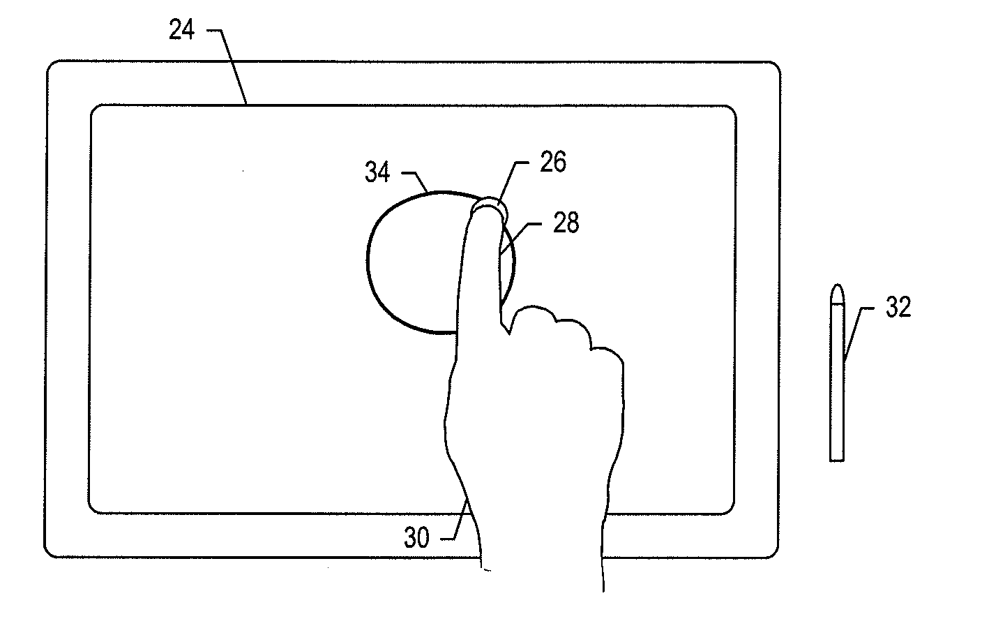
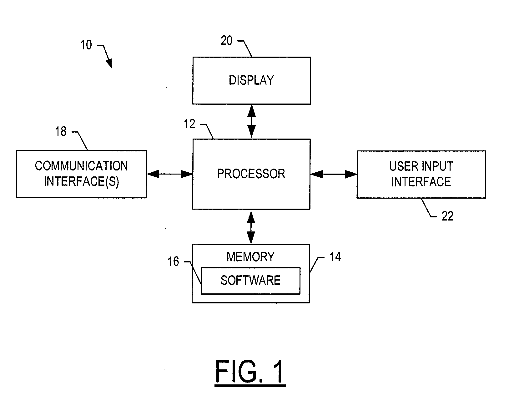
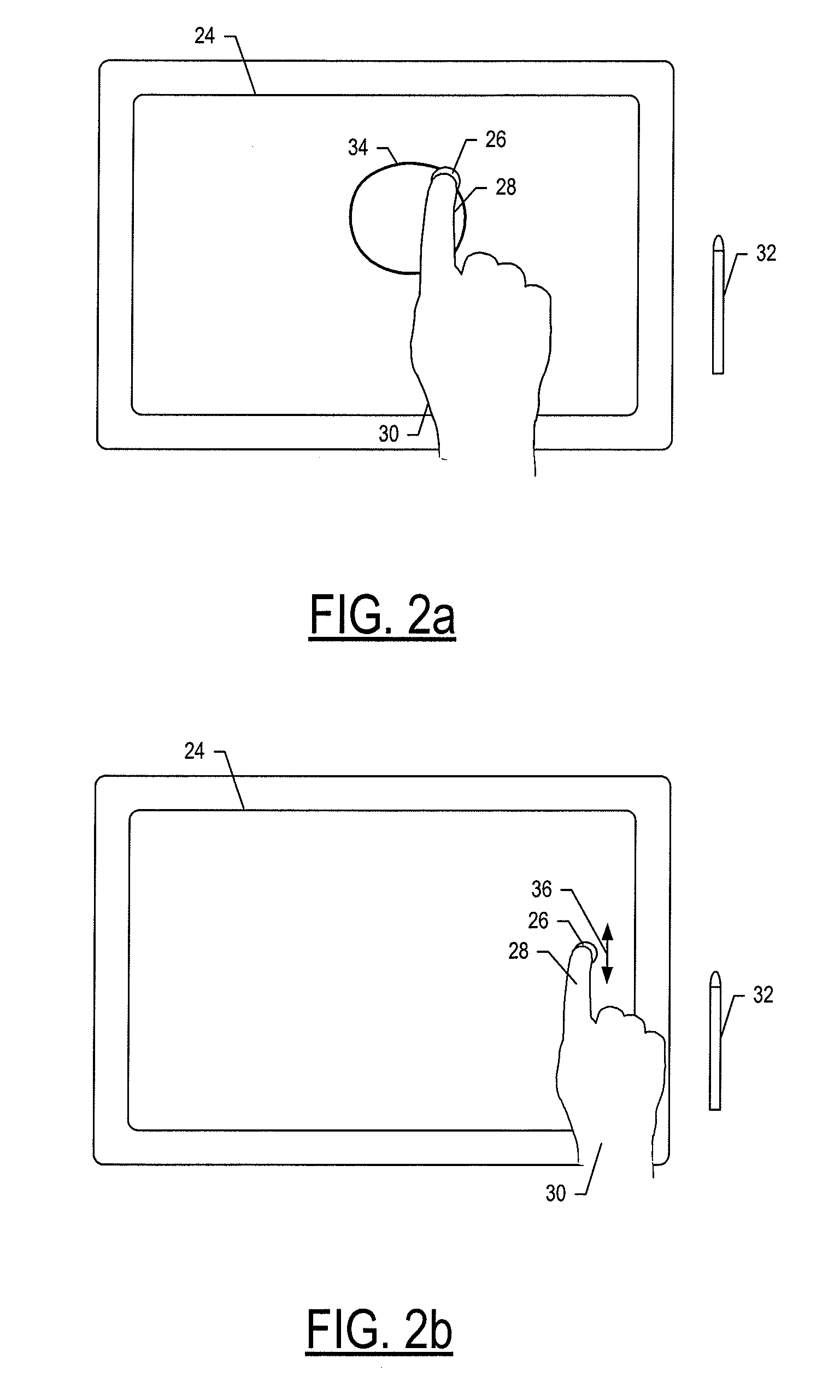
[0032]The present invention now will be described more fully hereinafter with reference to the accompanying drawings, in which preferred embodiments of the invention are shown. This invention may, however, be embodied in many different forms and should not be construed as limited to the embodiments set forth herein; rather, these embodiments are provided so that this disclosure will be thorough and complete, and will fully convey the scope of the invention to those skilled in the art. For example, references may be made herein to directions and orientations including vertical, horizontal, diagonal, right, left, up and down; it should be understood, however, that any direction and orientation references are simply examples and that any particular direction or orientation may depend on the particular object, and / or the orientation of the particular object, with which the direction or orientation reference is made. Like numbers refer to like elements throughout.

[0033]Referring to FIG. ...


PUM


Abstract

An apparatus is provided that includes a graphic overlay or display for a touch-sensitive surface with which an object comes into contact. The touch-sensitive surface is divided into a plurality of regions each of a number of which is associated with a distinct set of one or more of the plurality of gestures, where the plurality of gestures are associated with a respective plurality of functions of a software application operable by a processor. According to this aspect, the graphic overlay or display visibly depicts the regions and a layout of the regions into which the touch-sensitive surface is divided. The apparatus may further include a touch-feedback interface configured to provide touch feedback indicative of the gesture associated with the respective region within which the touch-feedback interface is disposed.

Description

CROSS-REFERENCE TO RELATED APPLICATIONS[0001]The present application is a continuation-in-part of U.S. patent application Ser. No. 12 / 718,717, entitled: Apparatus and Method for Directing Operation of a Software Application Via a Touch-Sensitive Surface Divided into Regions Associated with Respective Functions, filed Mar. 5, 2010, the content of which is hereby incorporated by reference in its entirety.FIELD OF THE INVENTION[0002]The present invention generally relates to a user interface and methods for interacting with a computer system, and more particularly, to a touch-based user interface and method for interacting with a medical-imaging system.BACKGROUND OF THE INVENTION[0003]In the field of medical imaging, prior to the digitization of medical imaging, medical-imaging users (e.g., Radiologists) would analyze physical film printed images in light boxes, and use physical devices such as magnifying glasses, rulers, grease pencils, and their hands to manipulate the physical print...

Claims


Application Information

Patent Timeline
Patent Type & Authority Applications(United States)
IPC IPC(8): G08B6/00G06F3/041
CPCG08B6/00G06F3/041G06F3/016G06F3/04883G06F3/04886G06F3/0488G06F2203/014G06F2203/04809
Inventor EDWARDS, CLIFF
Owner CHANGE HEALTHCARE HLDG LLC
Why Eureka
Try Eureka