Spa control with improved heater management system

a technology of management system and heater, which is applied in the direction of static/dynamic balance measurement, immersion heating arrangement, furnace, etc., can solve the problems of affecting the operation of the heater, etc., and achieves the effect of improving the control of the heater and the management system

Active Publication Date: 2011-09-15
BALBOA WATER GRP LLC
View PDF20 Cites 15 Cited by
  • Summary
  • Abstract
  • Description
  • Claims
  • Application Information

AI Technical Summary

Benefits of technology

[0013]Now, with a working sensor, the circulation pump is turned back on and the sensor is now watched for the effect of the cooling water. If, in a brief period, the sensor returns to a temperature near what it was before the heater was briefly energized, it is proven that flow exists. The recorded temperature at the sensor at this time is the second temperature measurement.

Problems solved by technology

This usage of pressure switches has the drawback that certain types of blockage can stop the flow of water but still indicate pressure in the plumbing from the pump.
Flow switches are somewhat expensive, however, and often unreliable.
A significant difference in temperature between the two sensors is an indication of a flow problem.
The first problem is that the difference in temperature between the two sensors is very small, even with significant blockage in the plumbing.
This approach cannot, therefore, be used with low-flow heaters, which are popular in the spa industry.
Another problem is that the spa water temperature is not known when the pump is off.
Clearly, this approach is not energy friendly.

Method used


Image

  • Spa control with improved heater management system
  • Spa control with improved heater management system
  • Spa control with improved heater management system

Examples


Embodiment Construction

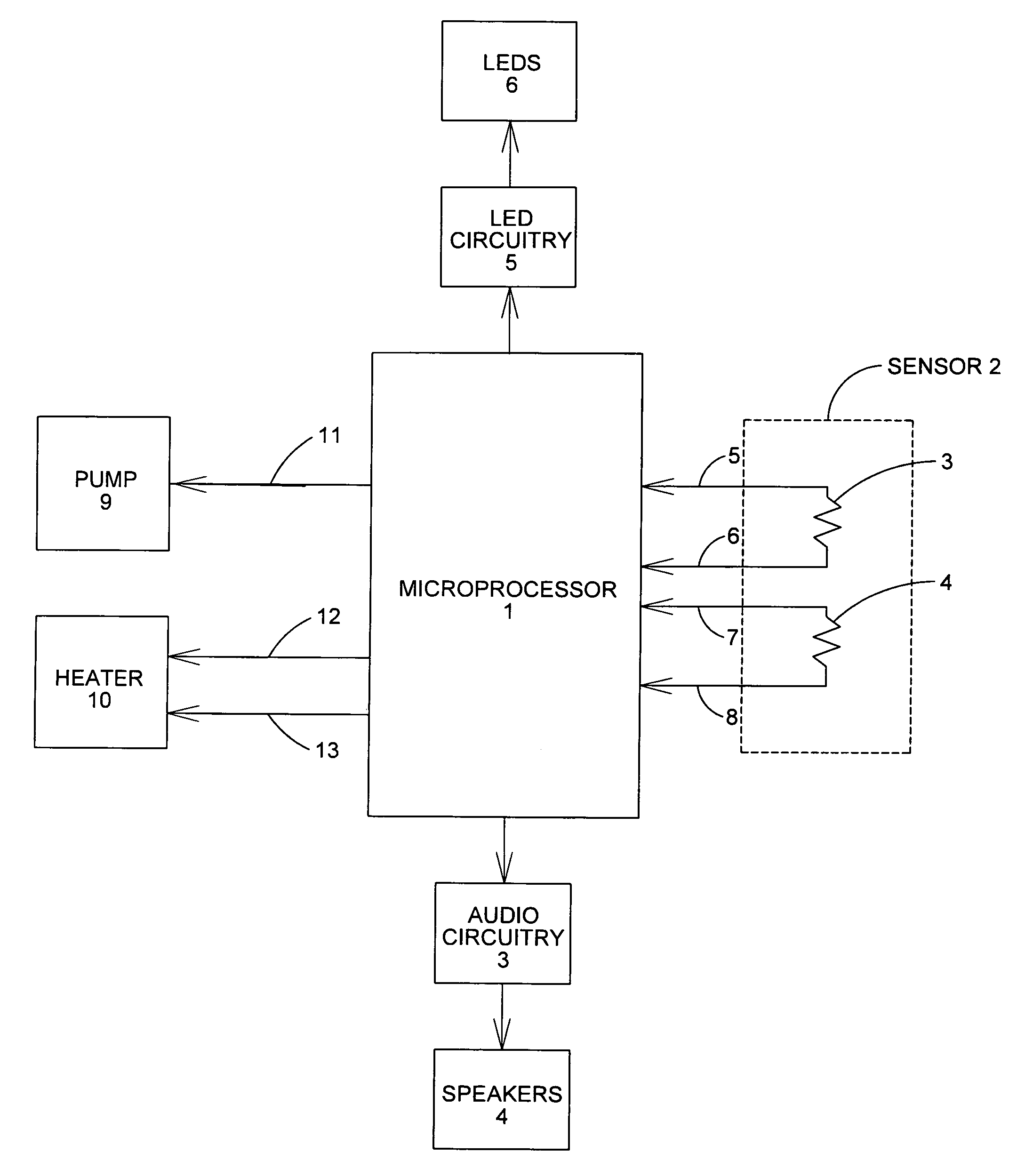
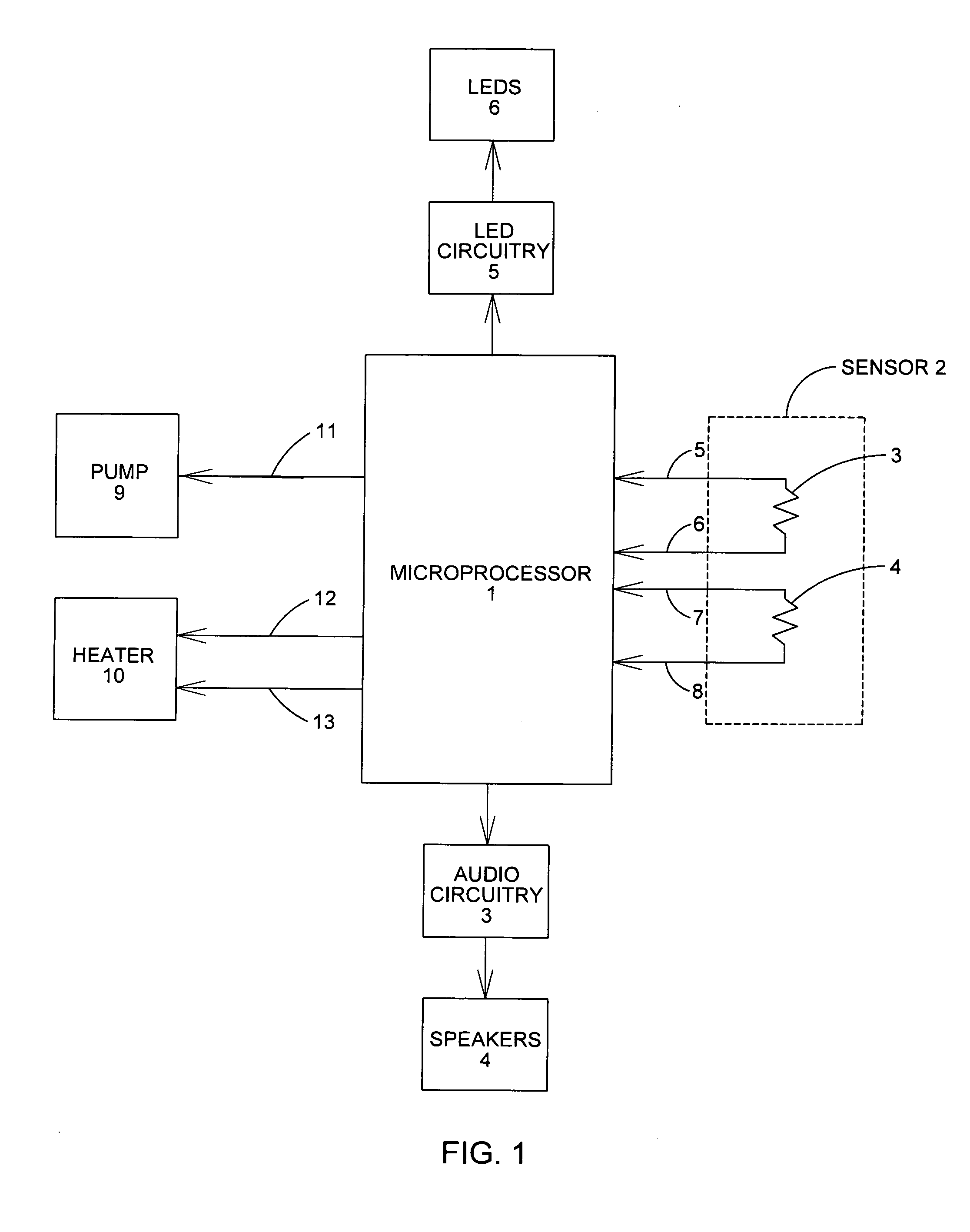
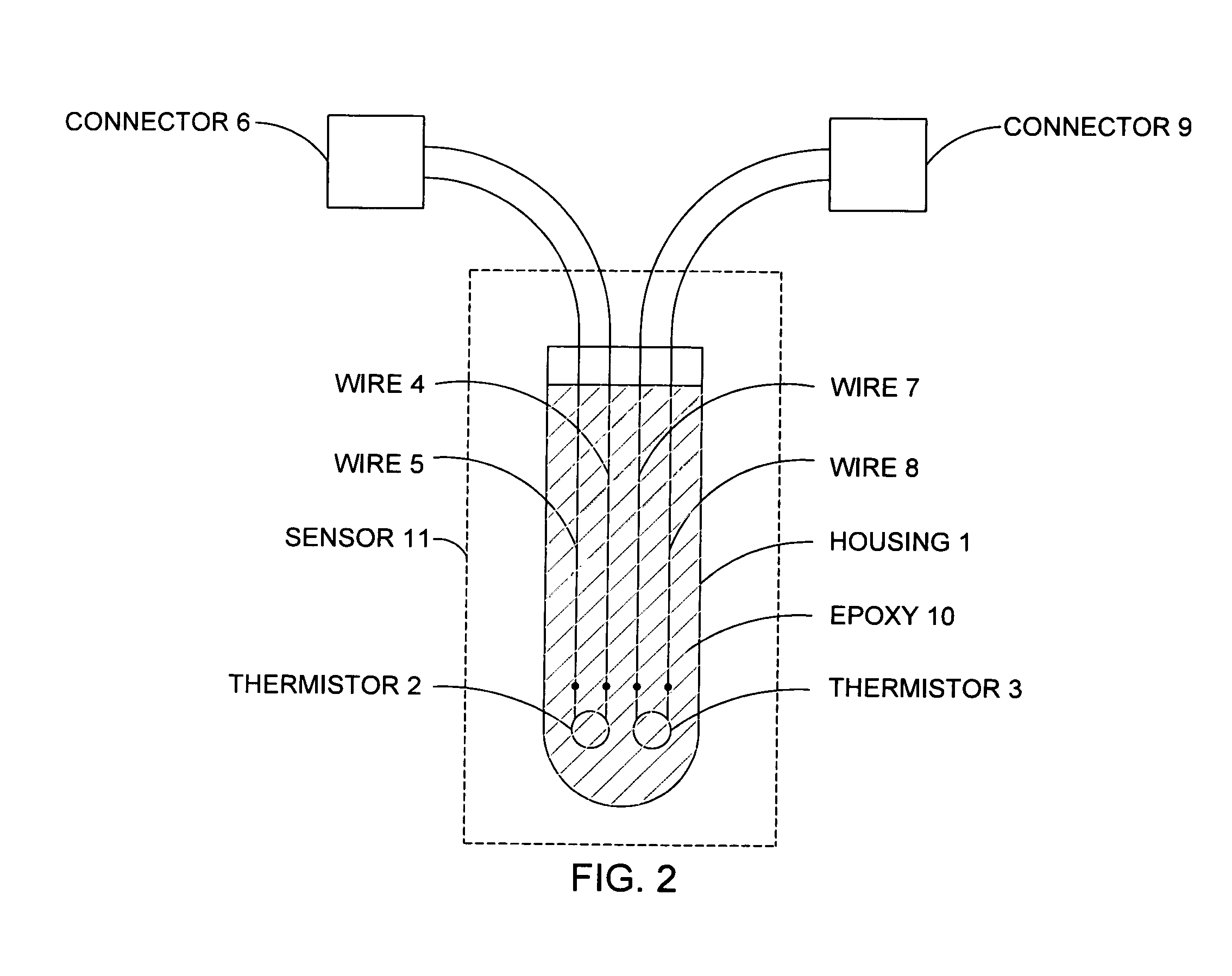
[0022]Referring now to FIG. 1, Sensor 2 is made up of dual, solid state temperature sensing elements Thermistor 3 and Thermistor 4 connected to separate input ports of Microprocessor 1 with wires 5, 6, 7, and 8. Thermistors 3 and 4 may share a common housing means, which is placed near the heating element of a spa heater. Both thermistors are not required for the invention but are included to meet the redundancy requirements of UL 1563 concerning independent circuits to control the heater. The measurements of the two thermistors may be averaged together for the purpose of controlling the water temperature. Since the thermistors are in exactly the same location, their temperature measurements should be nearly the same. If the two thermistors report measurements that are different by a prescribed amount, the microprocessor will de-energize the heater and indicate to the user that the sensor is defective.

[0023]In another, or the same, preferred embodiment, both measurements are constan...


PUM


Abstract

A spa control system that measures the flow of water through the heater of a spa and accurately reports water temperature in the spa using only one solid-state sensor in the heater. The working condition of the sensor is first determined by energizing the spa heater for a brief period of time, with the circulation pump de-energized, then quickly de-energizing the heater and watching for a heat rise at the sensor. A small rise is sufficient to proceed with the flow test. The flow rate is now determined by energizing the pump, with the heater still de-energized, and observing the rate at which the moving water cools the inside of the heater. If there is no circulation of water through the heater, the temperature of the sensor will continue to rise from the energy applied when the heater was briefly energized. This rise will be quite significant and a clear indication of a flow problem. Conversely, with normal flow, the inside of the heater will be cooled to approximately the same temperature as the spa water in just a few seconds. If the flow is found to be adequate, the heater may be energized for a normal period of time. Since, while cooling, a measured number of degrees is dropped in a measured number of seconds, a flow rate can be reported to the user as an estimate of gallons per minute. The sensor is now carefully monitored for a sudden increase in temperature, which would indicate loss of a normal flow of water. It is known that the temperature of the water in the spa will be within one or two degrees of the observed temperature at the sensor in the heater, even when the heater is energized. The water temperature can, therefore, be accurately reported to the user just from measuring the temperature of the water in the heater. The only problem with making all measurements at the heater is that the real water temperature is unknown when the pump is not running. This problem can result in short heating cycles, or create the need to run the pump several times per day just to check on the real water temperature. The present invention uses artificial intelligence to find the proper time to turn the pump back on at a time when the spa is just beginning to need heat. Any errors in finding this time are added back to subsequent calculations to make future cycles more accurate.

Description

[0001]This application is a continuation-in-part of an application filed by the same inventor on Sep. 23, 2010, titled “SPA CONTROL SYSTEM WITH IMPROVED FLOW MONITORING”.BACKGROUND OF THE INVENTION[0002]1. Field of the Invention[0003]This invention relates to spa control systems and, more particularity, to methods of measuring water flow through the heater of a spa, reporting flow status to the user, and monitoring spa water temperature in an energy-efficient manner.[0004]2. Discussion of Related Art[0005]For several years spa manufactures have been using two or more solid-state sensors to monitor water temperature in the spa as well as temperature somewhere near the heater. One sensor is needed to monitor temperatures at the heater according to the requirements in UL 1563, a standard for electric spas. Another sensor is usually located in the water of the spa to measure the temperature of the spa water.[0006]In conjunction with solid-state sensors, a flow-monitoring device has also...

Claims


Application Information

Patent Timeline
Patent Type & Authority Applications(United States)
IPC IPC(8): E04H4/00
CPCA61H33/005A61H2201/5082A61H2201/0207A61H33/0087A61H33/0095A61H2033/0054A61H2201/0228A61H2201/5007A61H2201/5048F24H9/2028F24H15/395F24H15/414F24H15/174F24H15/335F24H15/212F24H15/37
Inventor HOLLAWAY, JERRELL P.
Owner BALBOA WATER GRP LLC
Why Eureka
Try Eureka