Close-Spaced Leader-Follower Navigation Using Control Mimic

a technology of mimicry and leaderfollower, applied in the direction of instruments, computing, electric digital data processing, etc., can solve the problems of inability to respond to changes, inability to maintain the same path, and inherent delay between the leader the follower changing its speed and/or bearing

Active Publication Date: 2011-09-15
PERATON INC
View PDF11 Cites 42 Cited by
  • Summary
  • Abstract
  • Description
  • Claims
  • Application Information

AI Technical Summary

Benefits of technology

[0007]Briefly, a method is provided for automatically controlling a first vehicle (follower vehicle) that is to follow a second vehicle (leader vehicle) in a desired manner with respect to movement of the second vehicle. In the follower vehicle, bearing and acceleration control inputs are generated based on data representing bearing and acceleration control inputs made at the leader vehicle and a position of the follower vehicle relative to the leader vehicle so as to mimic in the follower vehicle the bearing and acceleration control inputs made in the leader vehicle.
[0008]According to one embodiment, the follower control method comprises three control loops. In a first control loop that has the lowest latency of the three control loops, the bearing and acceleration control inputs in the leader vehicle are monitored. Control status signals are generated representing the bearing and acceleration control inputs in the leader vehicle, and the control status signals are transmitted to the follower vehicle. The follower vehicle receives the control status signals from the leader vehicle and adjusts bearing and acceleration control inputs in the follower vehicle based on the control status signals received from the leader vehicle at a time so that t

Problems solved by technology

In current close leader-follower systems, the follower is too slow to respond to changes in speed and bearing of the leader.
Thus, there is an inherent delay between the leader changing its speed and/or bearing and the follower changing its speed and/or bearing.
This inherent delay causes poor performance in maintaining the same path as the leader and the proper follow distance unless the follow d

Method used


Image

  • Close-Spaced Leader-Follower Navigation Using Control Mimic
  • Close-Spaced Leader-Follower Navigation Using Control Mimic
  • Close-Spaced Leader-Follower Navigation Using Control Mimic

Examples


Embodiment Construction

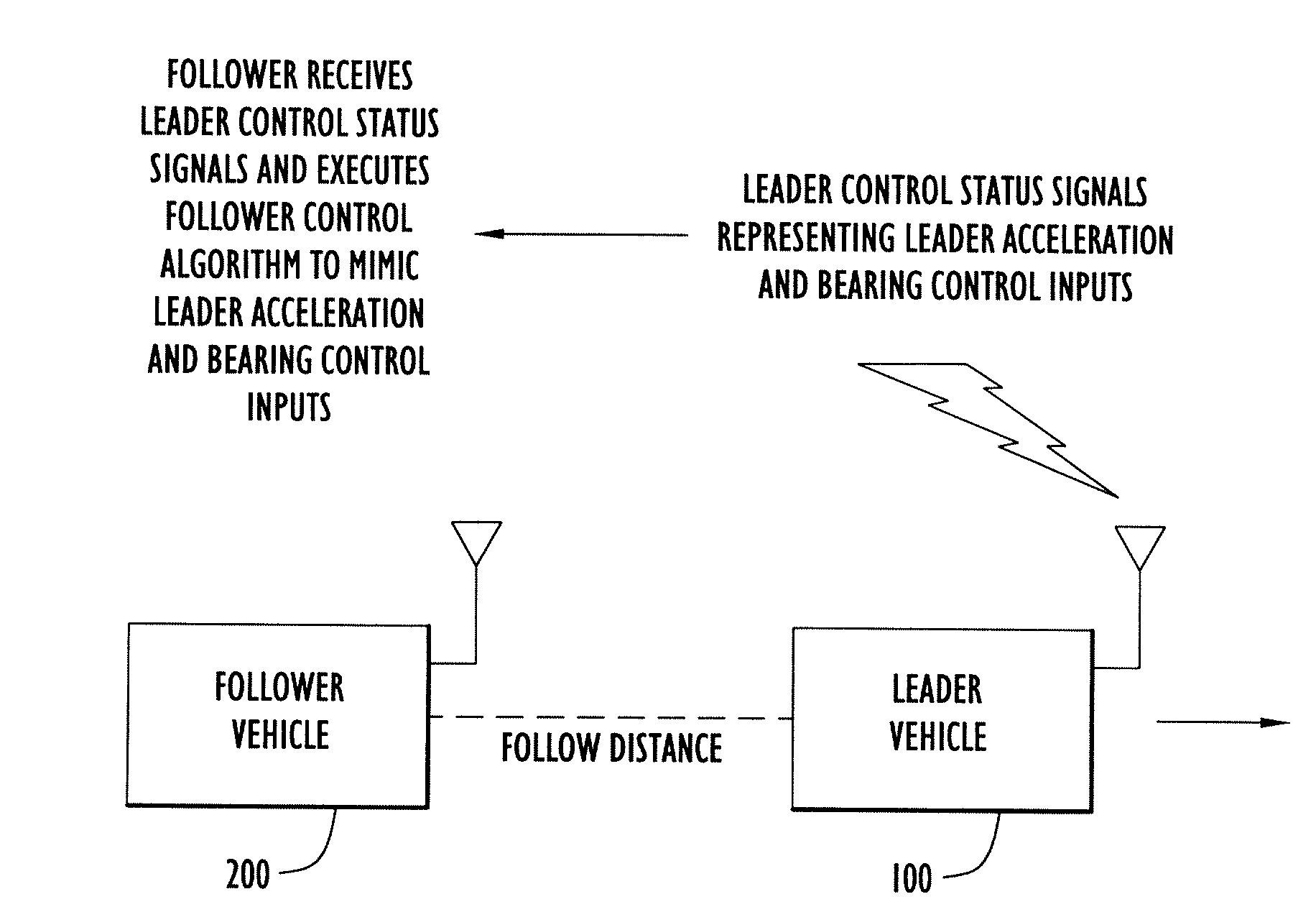
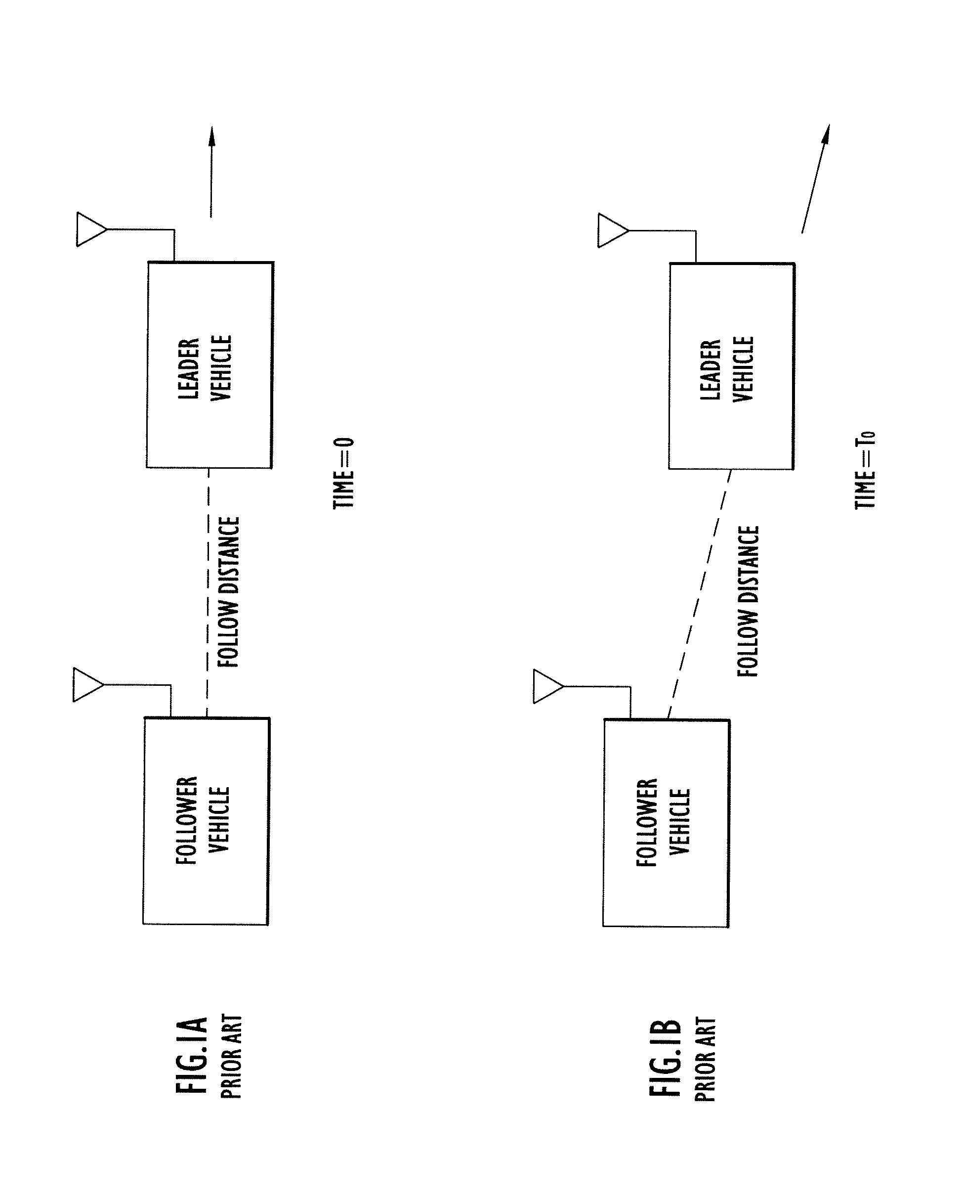
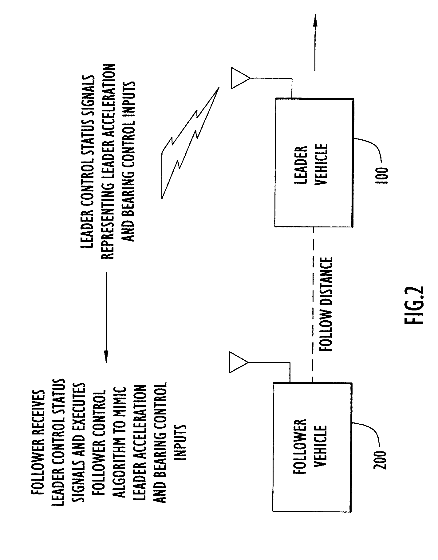
[0020]FIG. 2 illustrates a general block diagram of a leader-follower system according to an embodiment of the invention. The leader vehicle is shown at reference numeral 100 and the follower vehicle is shown at reference vehicle 200. It should be understood that there may be additional follower vehicles with respect to the leader vehicle 200, or with respect to one or more other follower vehicles. For simplicity, a single leader vehicle 100 and a single follower vehicle 200 are shown.

[0021]The leader vehicle 100 generates and transmits to the follower vehicle 200 leader control status signals that represent leader acceleration and bearing control inputs applied in the leader vehicle 100. The follower vehicle 200 receives the leader control status signals and executes a follower control algorithm with control mimic of the leader acceleration and bearing control inputs. In doing so, the follower vehicle 200 is able to maintain a consistent and desirable follow distance with respect t...


PUM


Abstract

A method is provided for automatically controlling a first vehicle (follower vehicle) that is to follow a second vehicle (leader vehicle) in a desired manner with respect to movement of the second vehicle. In the follower vehicle, bearing and acceleration control inputs are generated based on data representing bearing and acceleration control inputs made at the leader vehicle and a position of the follower vehicle relative to the leader vehicle so as to mimic in the follower vehicle the bearing and acceleration control inputs made in the leader vehicle. Adjustments may be made to the control inputs applied in the follower vehicle based on deviation between the velocity of the follower vehicle and velocity of the leader velocity, and on deviation between estimated (actual) follow distance and lateral offset and target follow distance and lateral offset between the follower vehicle and the leader vehicle.

Description

RELATED APPLICATION[0001]This application is a divisional of U.S. application Ser. No. 11 / 634,986, filed Dec. 7, 2006, the entirety of which is incorporated herein by reference.BACKGROUND OF THE INVENTION[0002]Vehicle leader-follower systems are used in various military and transportation applications in which one vehicle, called the “leader”, moves along the ground, in the air, or space, and one or more other vehicles, each called a “follower”, are to follow the leader and / or move along laterally displaced from the leader.[0003]A leader-follower system approach known in the art is one in which the follower follows closely behind or spaced from the leader, such as less than one second from the leader. In current close leader-follower systems, the follower is too slow to respond to changes in speed and bearing of the leader. The follower must first observe or be communicated the change in speed and bearing of the leader before providing inputs to its controls to adjust its own trajec...

Claims


Application Information

Patent Timeline
IPC IPC(8): G06F7/00
CPCG05D1/0295
Inventor FARWELL, MARK LALONSELDOMRIDGE, CHAD MARTINLARSON, ROBERT ERIC
Owner PERATON INC
Why Eureka
Try Eureka