
Apparatus and method for aligning an antenna in a reference position

a reference position and antenna technology, applied in the direction of collapsible antennas, antennas, large fixed members, etc., can solve the problems of multipath errors, significant degradation of signal quality, and inability to ensure the alignment of the system along a plan

Active Publication Date: 2011-09-22
MULTIWAVE SENSORS
View PDF4 Cites 22 Cited by
  • Summary
  • Abstract
  • Description
  • Claims
  • Application Information

AI Technical Summary

Benefits of technology

[0012]In another aspect, the present disclosure relates to a method for retaining an antenna that is secured to an apparatus in a reference position during alignment of the antenna, said method comprising the following steps: a user attaching the antenna to the apparatus by a securing means in a manner that causes a back wall of the

Problems solved by technology

Even small errors in the azimuth alignment will cause a significant degradation in signal quality.
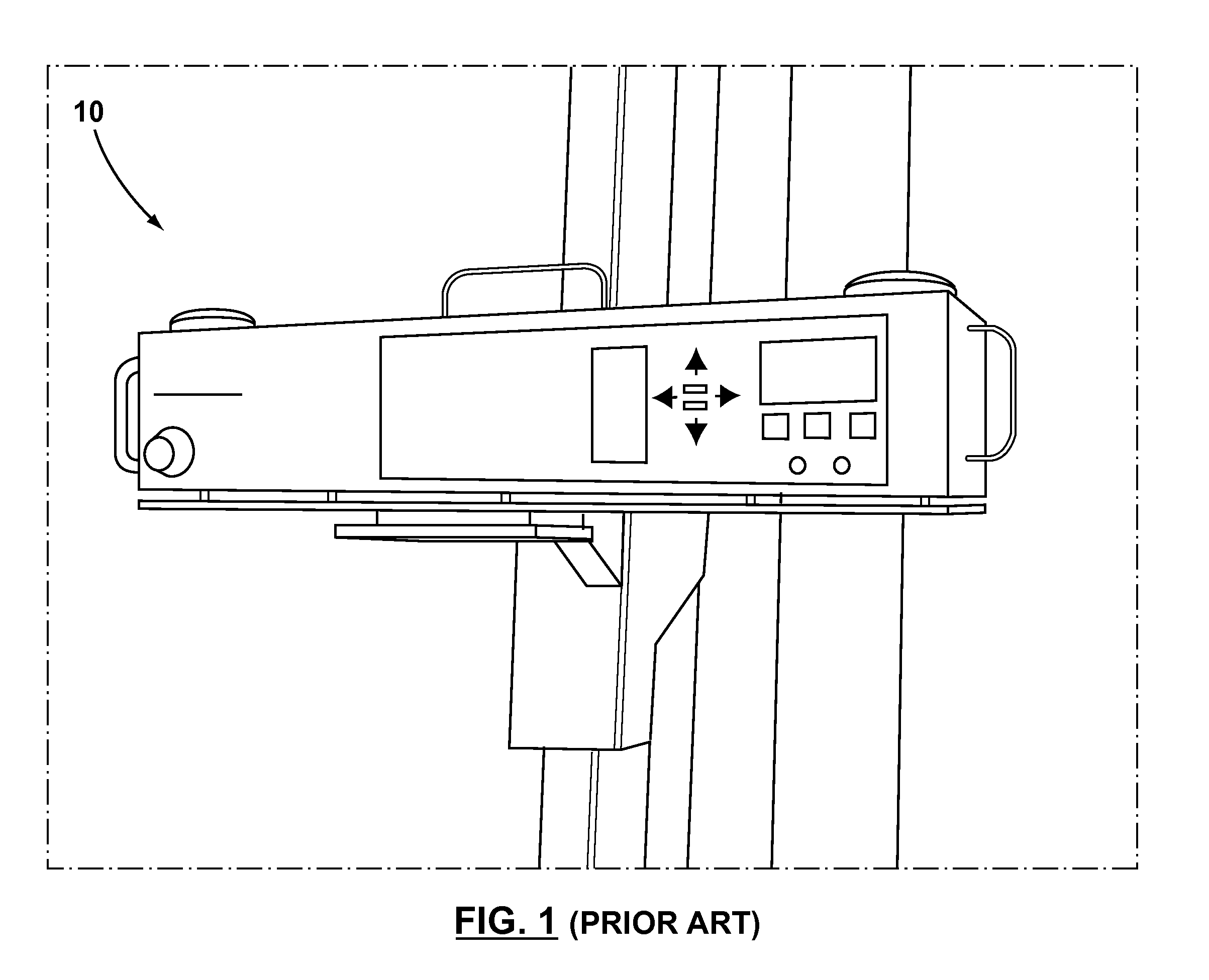
When mounted to the side of the antenna (see FIG. 1), multipath errors are introduced because the GPS antenna are disposed below the antenna to be aligned.
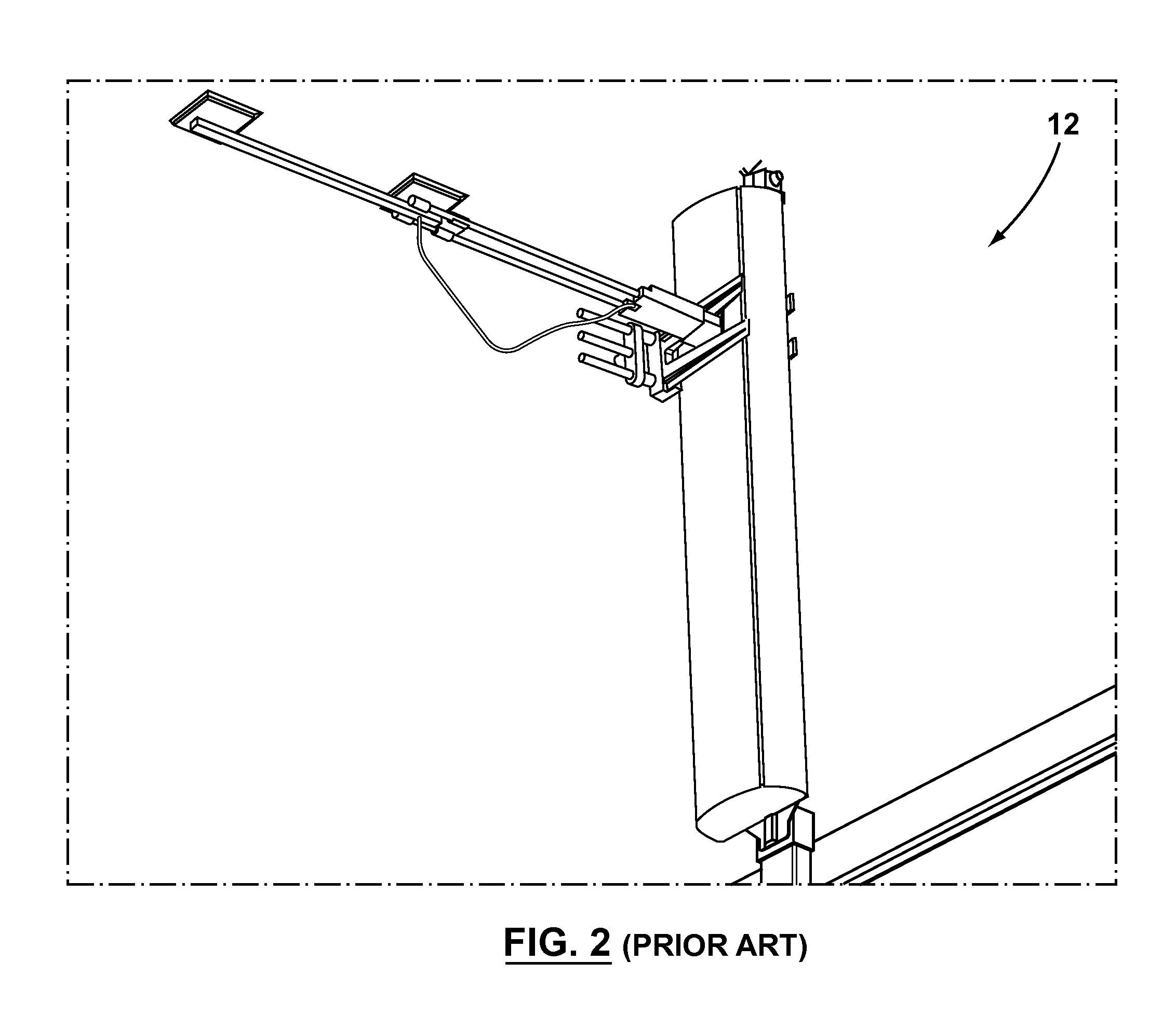
When mounted on top of the antenna to be aligned, there can be no guarantee that the system is aligned along a plane from which azimuth is measured, as the top of the antenna may not be completely flat or parallel to such a plane.
Furthermore, the system includes a plurality of buttons that, when pressed with any force, will cause the system to be out of alignment.
However, the shape and configuration of antennae cause a problem for the SPAA to provide precise alignment.
Maintaining the two arms in exact parallel alignment is very difficult and even a small misalignment can produce an inaccurate result.
Aligning a pointing device with the front panel can never guarantee that the back panel is aligned.
Thus, alignment of the front panel will not necessarily provide the optimal antenna alignment.

Method used


Image

  • Apparatus and method for aligning an antenna in a reference position
  • Apparatus and method for aligning an antenna in a reference position
  • Apparatus and method for aligning an antenna in a reference position

Examples


Embodiment Construction

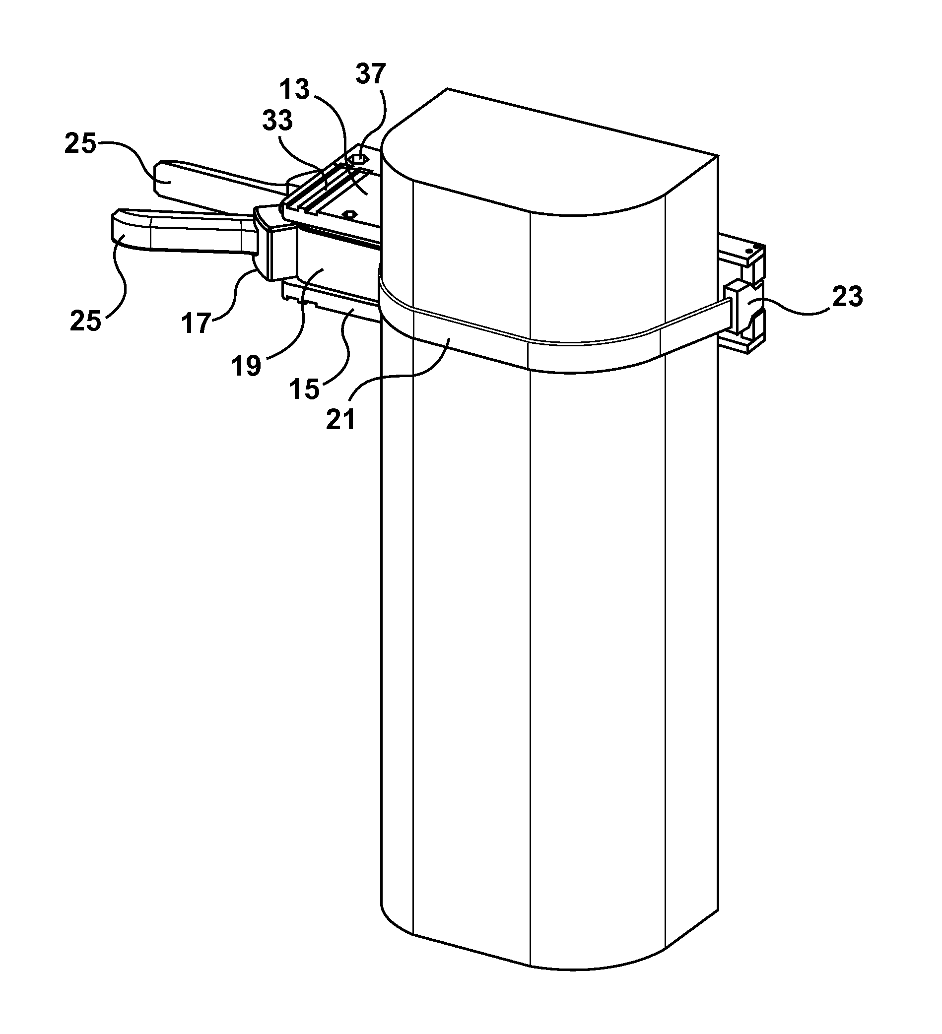
[0034]The present invention is an apparatus operable to align an antenna and to retain the antenna in a reference position during alignment of the antenna. The apparatus may include a bracket, or mounting brace, having an arm attached thereto, and the arm conforms to the back wall of an antenna. An engagement means and / or securing means may be incorporated in the apparatus to retain the position of the antenna in a fixed or removeable connection with the apparatus. An alignment device being operable to align the antenna may be attached to the bracket. The apparatus of the present invention may be arranged or otherwise positioned in accordance with a reference position. Said reference position may be defined as a position that is selected in reference to a reference point, line, or plane of the antenna. The apparatus may retain the antenna in a reference position during alignment of the antenna.

[0035]The present invention may be an apparatus for aligning an antenna. For example, the ...


PUM

PropertyMeasurementUnit
Widthaaaaaaaaaa

Abstract

The present invention is an apparatus operable to align an antenna and to retain the antenna in a reference position during alignment of the antenna. The apparatus may include a bracket having an arm attached thereto, and the arm conforms to the back wall of an antenna. An engagement means and / or securing means may be incorporated in the apparatus to retain the position of the antenna in a fixed or removeable connection with the apparatus. An alignment device being operable to align the antenna may be attached to the bracket. The apparatus of the present invention may be arranged or otherwise positioned in accordance with a reference position. Said reference position may be defined as a position that is selected in reference to a reference point, line, or plane of the antenna. The apparatus may retain the antenna in a reference position during alignment of the antenna.

Description

[0001]This application claims the benefit of U.S. Provisional Patent Application Ser. No. 61 / 315,581 filed Mar. 19, 2010.FIELD OF THE INVENTION[0002]The present invention relates to an apparatus for antenna positioning, and more specifically to an apparatus for maintaining an antenna in a specific position.BACKGROUND OF THE INVENTION[0003]Wireless communications enable information to be exchanged using wireless devices, such as cellular telephones and Internet-enabled smart phones. With the ever-increasing demand for wireless bandwidth, it is becoming increasingly important to ensure that wireless networks are optimally deployed.[0004]Typically, wireless communication networks comprise a plurality of telecommunications antennae mounted high above antenna masts, transmission towers, and tall buildings. Each antenna is typically a panel antenna designed to serve a specific area, which in the case of cellular communications is referred to as a cell. The strength of the signal available...

Claims


Application Information

Patent Timeline
IPC IPC(8): H01P11/00B23Q1/25
CPCH01Q1/1207H01Q1/125Y10T29/5313Y10T29/49004Y10T29/49016
Inventor CLIFFORD, BRUCE KENNETHFRISCHMAN, MARK
Owner MULTIWAVE SENSORS
Learn More