Walk-in outdoor electronic equipment enclosure

Inactive Publication Date: 2011-09-22
INTEL CORP
View PDF4 Cites 20 Cited by
  • Summary
  • Abstract
  • Description
  • Claims
  • Application Information

AI Technical Summary

Problems solved by technology

However, this approach exposes the technicians and the electronic equipment to the

Method used


Image

  • Walk-in outdoor electronic equipment enclosure
  • Walk-in outdoor electronic equipment enclosure
  • Walk-in outdoor electronic equipment enclosure

Examples


Embodiment Construction

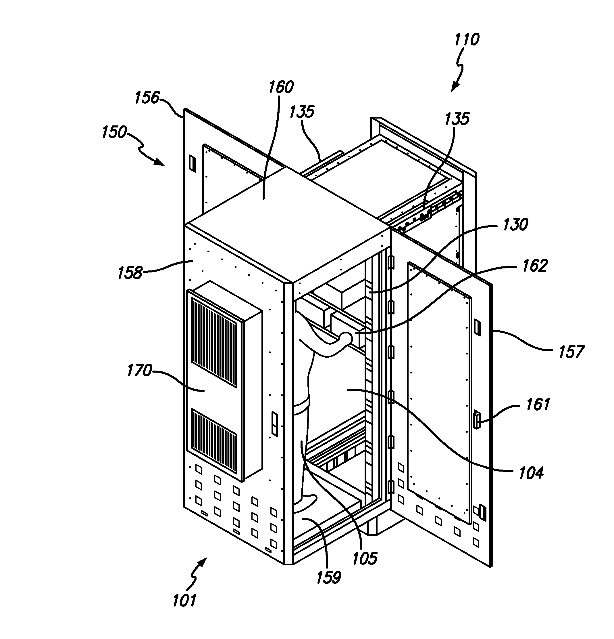
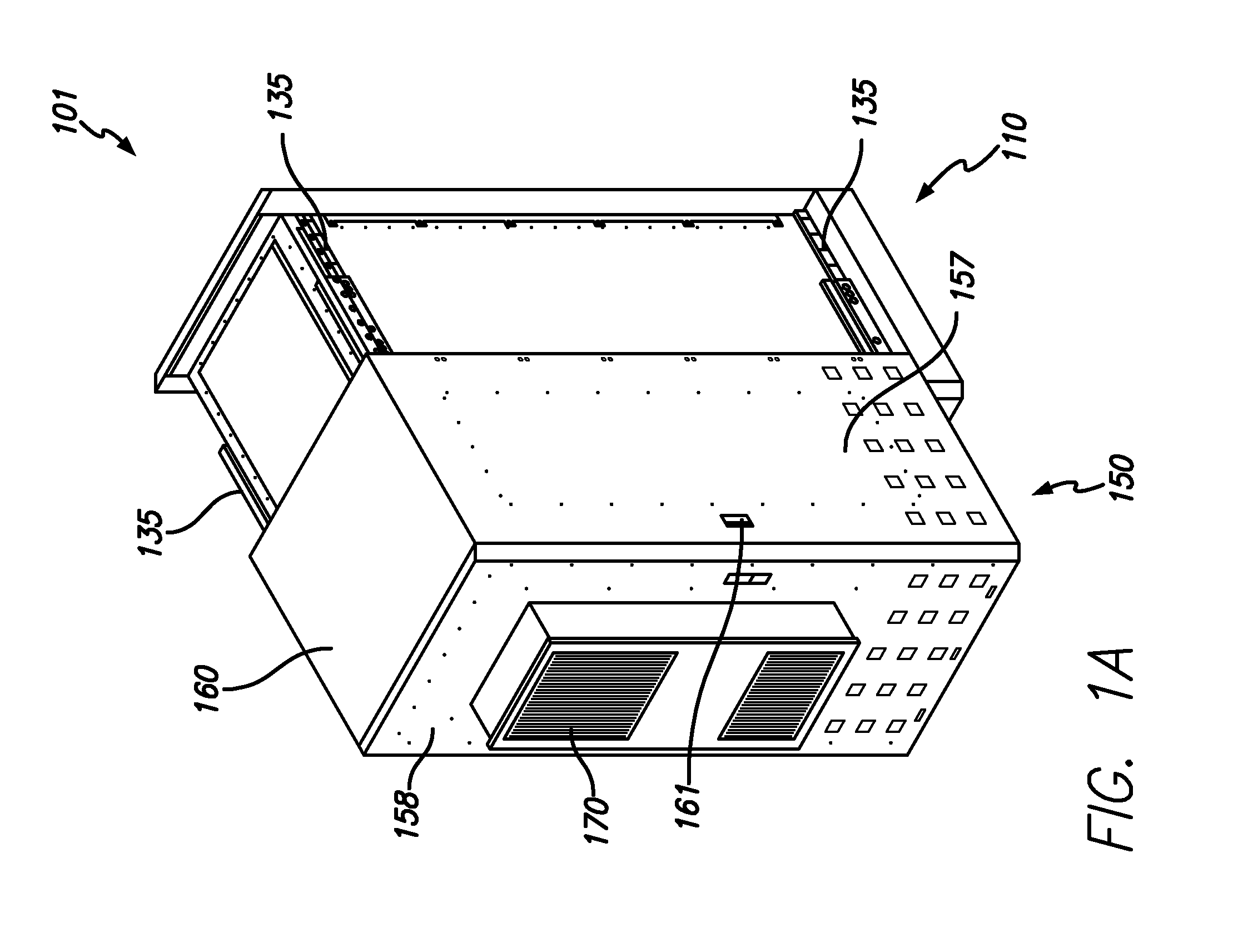
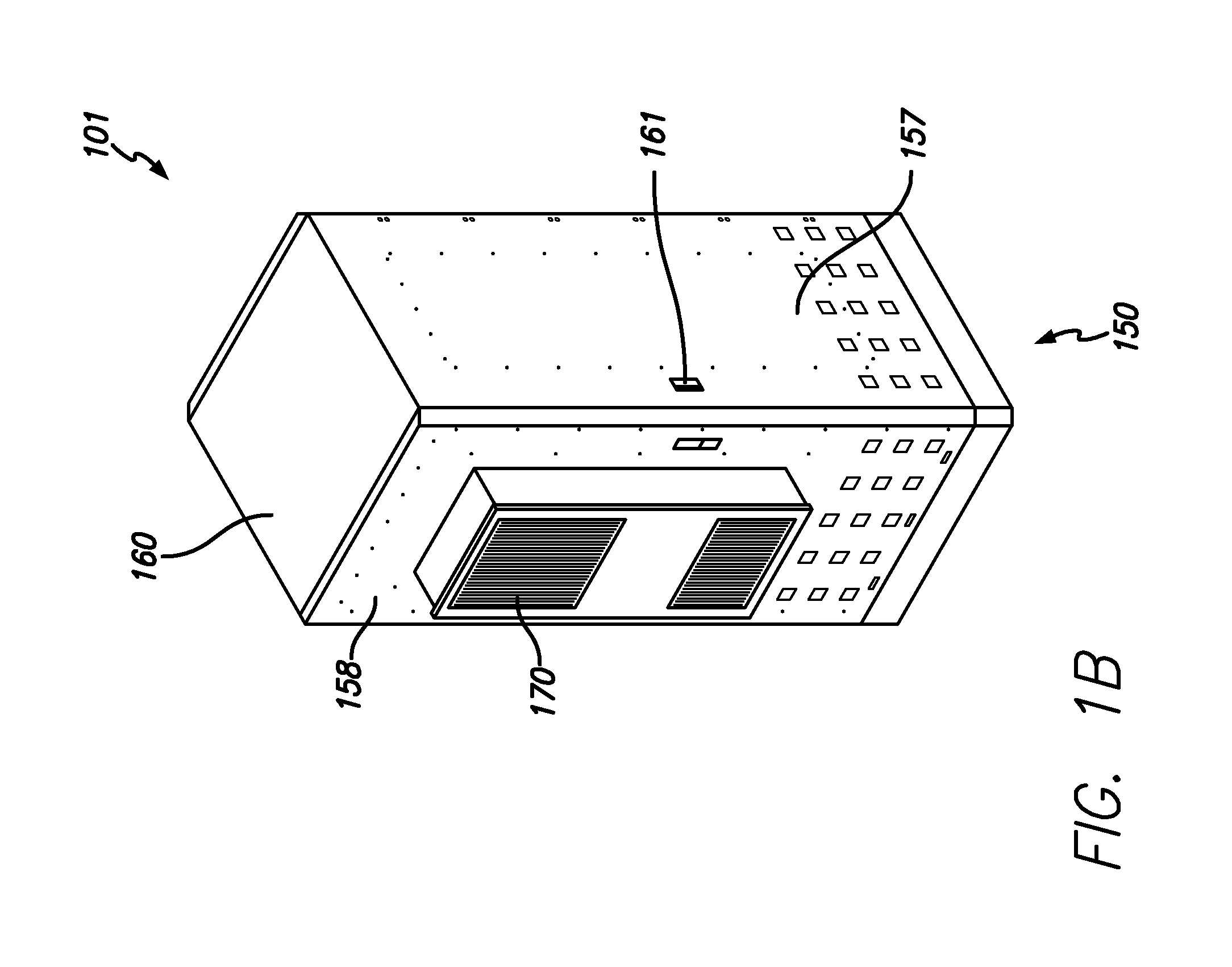
[0022]It is an object of the present invention to provide a temporary, sheltered service access area for an outdoor electronics enclosure. The outdoor electronics enclosure comprises a fixed cabinet which holds electronic equipment and a housing that is attached to the fixed cabinet with slide rails. The housing has a top panel, a service access door, two vertical panels, and a raised floor. The housing is movable from a closed position to an open position. When the housing is in a closed position, the housing is placed immediately adjacent to and partially surrounds the fixed cabinet. When the housing is placed in an open position, the housing is moved away from the fixed cabinet in a horizontal direction to define an internal service access area within the housing for servicing the electronic equipment. During standard operation, the housing is placed in the closed position. When the electronic equipment is to be maintained, a service technician pulls the housing to the open posit...


PUM


Abstract

An enclosure that provides a temporary sheltered service access area is disclosed. The outdoor electronics enclosure comprises a fixed cabinet which holds electronic equipment and a housing that is attached to the fixed cabinet with slide rails. The housing has a top panel, a service access door, two vertical panels, and a raised floor. The housing is movable from a closed position in which the housing is immediately adjacent to and partially surrounds the fixed cabinet to an open position in which the housing is moved away from the fixed cabinet in a horizontal direction to define an internal service access area within the housing for servicing the electronic equipment. Service technicians enter the sheltered service area and maintain electronic equipment in the fixed cabinet.

Description

RELATED APPLICATION INFORMATION[0001]The present application claims priority under 35 U.S.C. Section 119(e) to U.S. Provisional Patent Application Ser. No. 61 / 314,525 filed Mar. 16, 2010, the disclosure of which is incorporated herein by reference in its entirety.BACKGROUND OF THE INVENTION[0002]1. Field of the Invention[0003]The present invention relates generally to outdoor enclosures for holding and sheltering electronic equipment. More particularly, the invention relates to outdoor enclosures having electronic equipment requiring access for maintenance of the equipment.[0004]2. Description of the Prior Art and Related Background Information[0005]Modern telecommunication systems utilize outdoor cabinets to house electronic equipment. Servicing the equipment typically requires technicians to open doors on the outdoor cabinets to gain access to the electronic equipment. However, this approach exposes the technicians and the electronic equipment to the outdoor environment which may ...

Claims


Application Information

Patent Timeline
IPC IPC(8): H05K5/06H05K5/00H05K7/20
CPCH04Q1/10H05K7/206H05K7/186
Inventor MACKIN, CHRISTIAN CAMPBELL
Owner INTEL CORP
Why Eureka
Try Eureka