Dispensing control device for icemaker

Inactive Publication Date: 2011-09-22
ZIPPY TECH
View PDF8 Cites 8 Cited by
  • Summary
  • Abstract
  • Description
  • Claims
  • Application Information

AI Technical Summary

Benefits of technology

[0008]The object of the present invention is to solve the problems described above by integrating multiple dispensing outlets and thus reducing the volume of the dispensing machine, so as to facilitate the operation of the user.
[0009]For achieving the object described above, the present invention provides a dispensing control device for an icemaker including a dispensing structure and a control structure assembled with the dispensing structure. The dispensing structure includes at least a first dispensing portion and a second dispensing portion for dispensing at least two kinds of materials, and a dispensing area with a first position and a second position defined therein respectively corresponding to the first and the second dispensing portion. The control structure includes a first trigger unit and a second trigger unit, for respectively triggering the corresponding first and second dispensing portion to dispense materials respectively. The f

Problems solved by technology

1. Because the ice and the liquid dispensing outlets are arranged side by side, a larger space will be occupied, so that if the dispenser is designed to integrate with the refrigerator, the inner space of the refrigerator might be reduced thereby. And, if it keeps the inner space of the refrigerator unreduced, the entire volume of the refrigerator must be increased.
2. If the dispenser is applied to the beverage machine for dispensing multiple kinds of beverages, th

Method used


Image

  • Dispensing control device for icemaker
  • Dispensing control device for icemaker
  • Dispensing control device for icemaker

Examples


Embodiment Construction

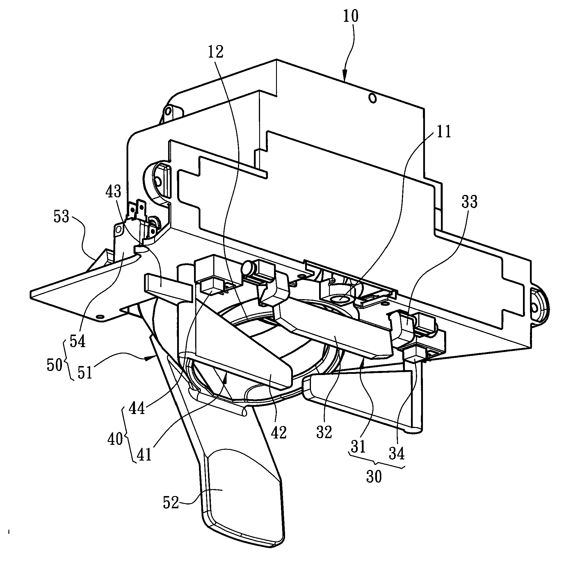
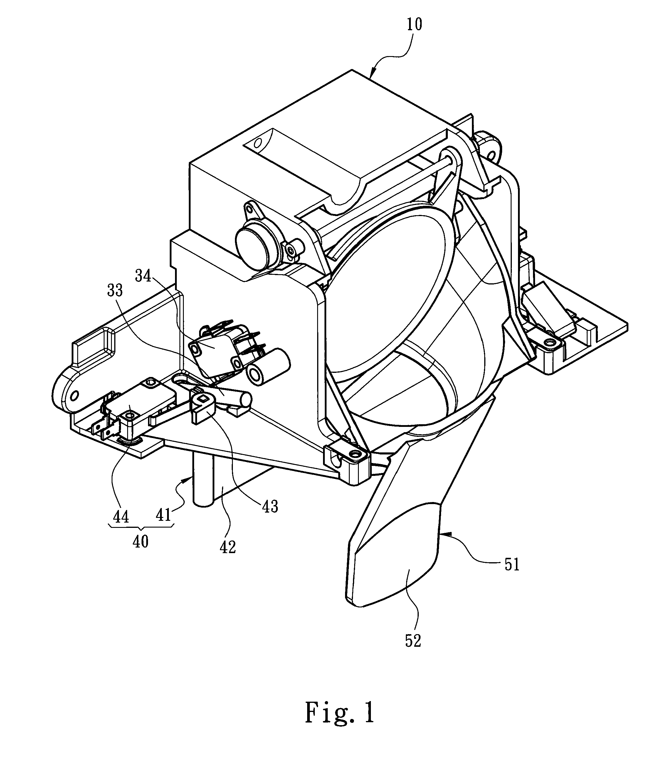
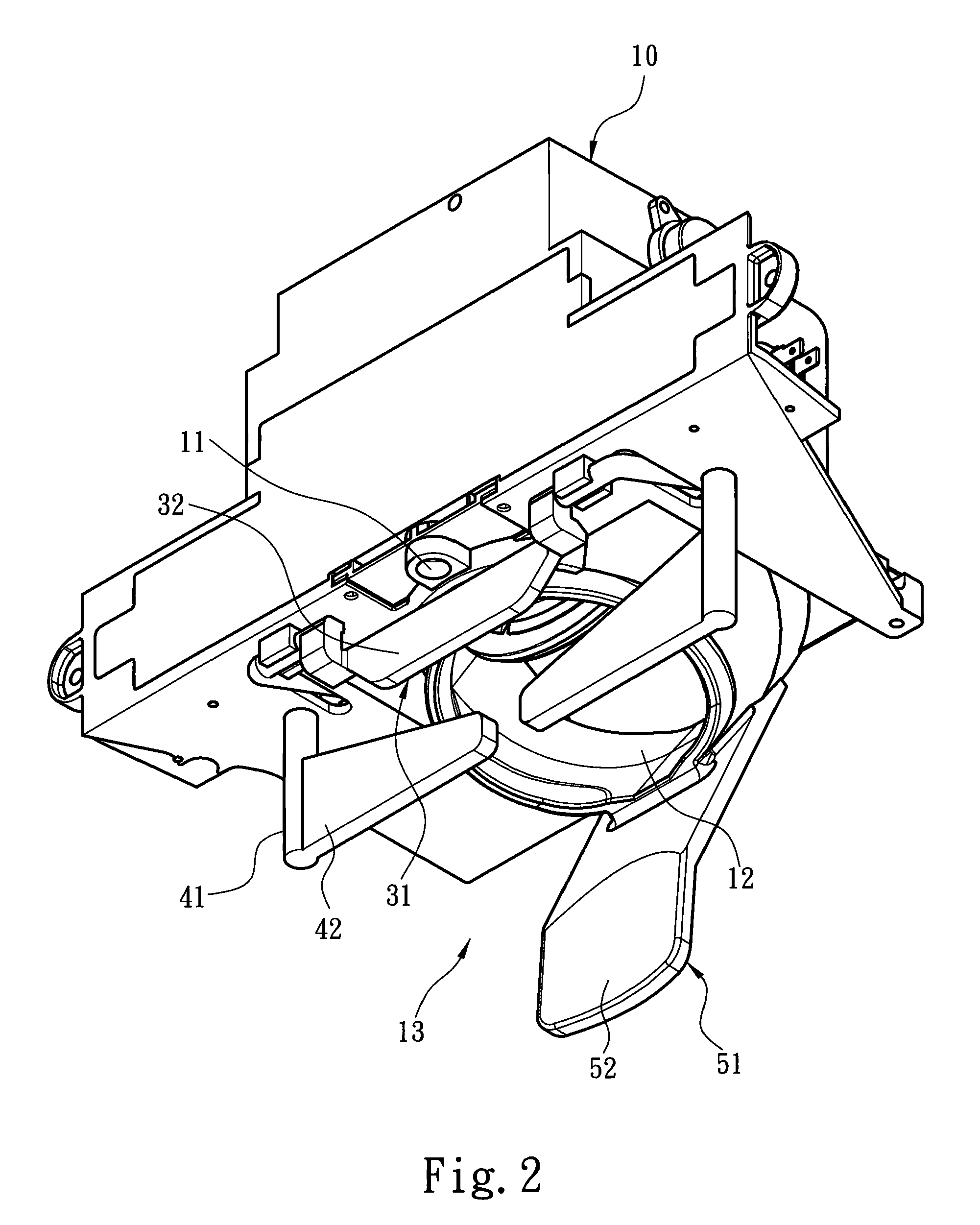
[0020]Please refer to FIG. 1 and FIG. 2, which show a dispensing control device for an icemaker according to the present invention. The dispensing control device includes a dispensing structure 10. The dispensing structure includes at least a first dispensing portion 11 and a second dispensing portion 12, e.g., material outlets, for dispensing at least two kinds of materials, and the dispensing structure 10 is also formed to have a dispensing area 13 in which a first position and a second position are respectively defined. Then, as shown FIG. 3, the dispensing control device also includes a control structure, which includes a first trigger unit 30 and a second trigger unit 40, for respectively triggering the corresponding first and second dispensing portion 11, 12 to dispense the materials respectively thereof. The first trigger unit 30 includes a first actuating element 31 mounted at the first position in the dispensing area 13, and a first trigger component 34 which can be trigger...


PUM


Abstract

A dispensing control device for an icemaker includes a dispensing structure and a control structure assembled with the dispensing structure. The dispensing structure includes at least a first dispensing portion and a second dispensing portion for dispensing at least two kinds of materials, wherein the first and the second dispensing portion and the dispensing structure form a dispensing area in which a first position and a second position are defined respectively. The control structure includes a first trigger unit and a second trigger unit, for respectively triggering the corresponding first and second dispensing portion to dispense materials respectively thereof, wherein the first and the second trigger units respectively include a first and a second actuating element mounted at the first position and the second position in the dispensing area, and a first and a second trigger components which are respectively triggered by the first and the second actuating elements to control the material dispensing of the first and second dispensing portion. Therefore, the user can obtain different desired materials by operating at different positions in the dispensing area.

Description

FIELD OF THE INVENTION[0001]The present invention is related to a dispensing control device for an icemaker, and more particularly to a dispensing control device which can control the icemaker to dispense liquids or solids.BACKGROUND OF THE INVENTION[0002]The dispensing control device which can control the dispensing of liquids or solids (e.g., ice cubes) provides great convenience for the industrial or home users. This type of dispensing control device is always applied to the loading machine in the beverage store, the beverage dispenser in the fast food restaurant, the water / ice dispenser mounted on the refrigerator, the coffee maker and the water dispenser etc.[0003]Some prior arts, like U.S. Pat. No. 7,266,951, U.S. Pat. No. 7,104,085, and U.S. Pat. No. 5,050,777, disclosed a dispensing device for the refrigerator or the beverage machine, and the feature they have in common is that the dispensing device has an ice dispensing outlet and one or more liquid dispensing outlet aside ...

Claims


Application Information

Patent Timeline
IPC IPC(8): F25C5/00
CPCF25C5/002F25C5/20
Inventor CHOU, CHIN-WEN
Owner ZIPPY TECH
Why Eureka
Try Eureka