Tube Cutter with Automatically Feeding Function and with Enhanced Torque

a tube cutter and torque technology, applied in the field of tube cutters, can solve the problems of wasting user's energy and time, inconvenient operation, waste of energy and working time, etc., and achieve the effect of convenient user operation of the tube cutter, easy and convenient cutting of tubes

Active Publication Date: 2019-03-21
LIAO BING CHENG
View PDF19 Cites 0 Cited by
  • Summary
  • Abstract
  • Description
  • Claims
  • Application Information

AI Technical Summary

Benefits of technology

[0006]According to the primary advantage of the present invention, the driving handle is combined with the rotation portion of the guide bolt to enhance the torque of the tube cutter when shearing the tube, so that the operator cuts the tube easily and conveniently.
[0007]According to another advantage of the present invention, the holder is pushed by the elastic force of the elastic members, so that the cutting wheel is fed toward the tube automatically during the cutting process, so as to shear the tube successively until the tube is cut, thereby facilitating the user operating the tube cutter when cutting the tube.
[0008]Further benefits and advantages of the present invention will become apparent after a careful reading of the detailed description with appropriate reference to the accompanying drawings.
[0009]FIG. 1 is a perspective view of a tube cutter in accordance with the first preferred embodiment of the present invention.
[0010]FIG. 2 is an exploded perspective view of the tube cutter in accordance with the first preferred embodiment of the present invention.
[0011]FIG. 3 is a cross-sectional view of the tube cutter in accordance with the first preferred embodiment of the present invention.

Problems solved by technology

However, the conventional tube cutter does not have an automatically feeding function so that the user has to rotate the control knob successively to move the two rollers to press the tube during the shearing process, thereby causing inconvenience to the user, and thereby wasting the energy and working time.
In addition, the conventional tube cutter has a small torque so that the user has to apply a large force on the main body to rotate the main body is held by the user's hand and is rotated relative to the tube, so that the cutting wheel is revolved on the tube so as to shear the tube relative to the tube so as to shear the tube, thereby wasting the user's energy and time.

Method used


Image

  • Tube Cutter with Automatically Feeding Function and with Enhanced Torque
  • Tube Cutter with Automatically Feeding Function and with Enhanced Torque
  • Tube Cutter with Automatically Feeding Function and with Enhanced Torque

Examples


Embodiment Construction

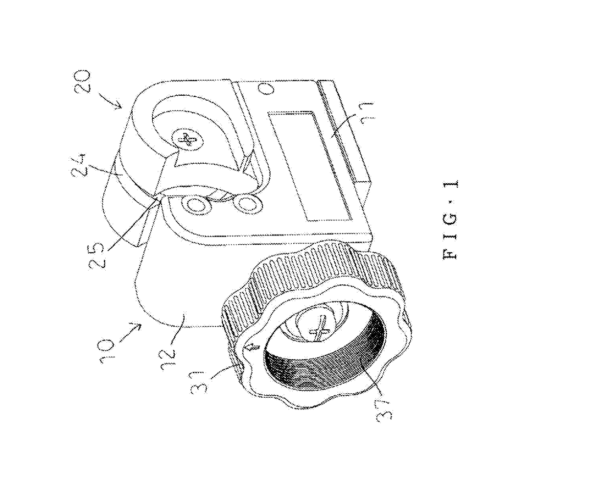
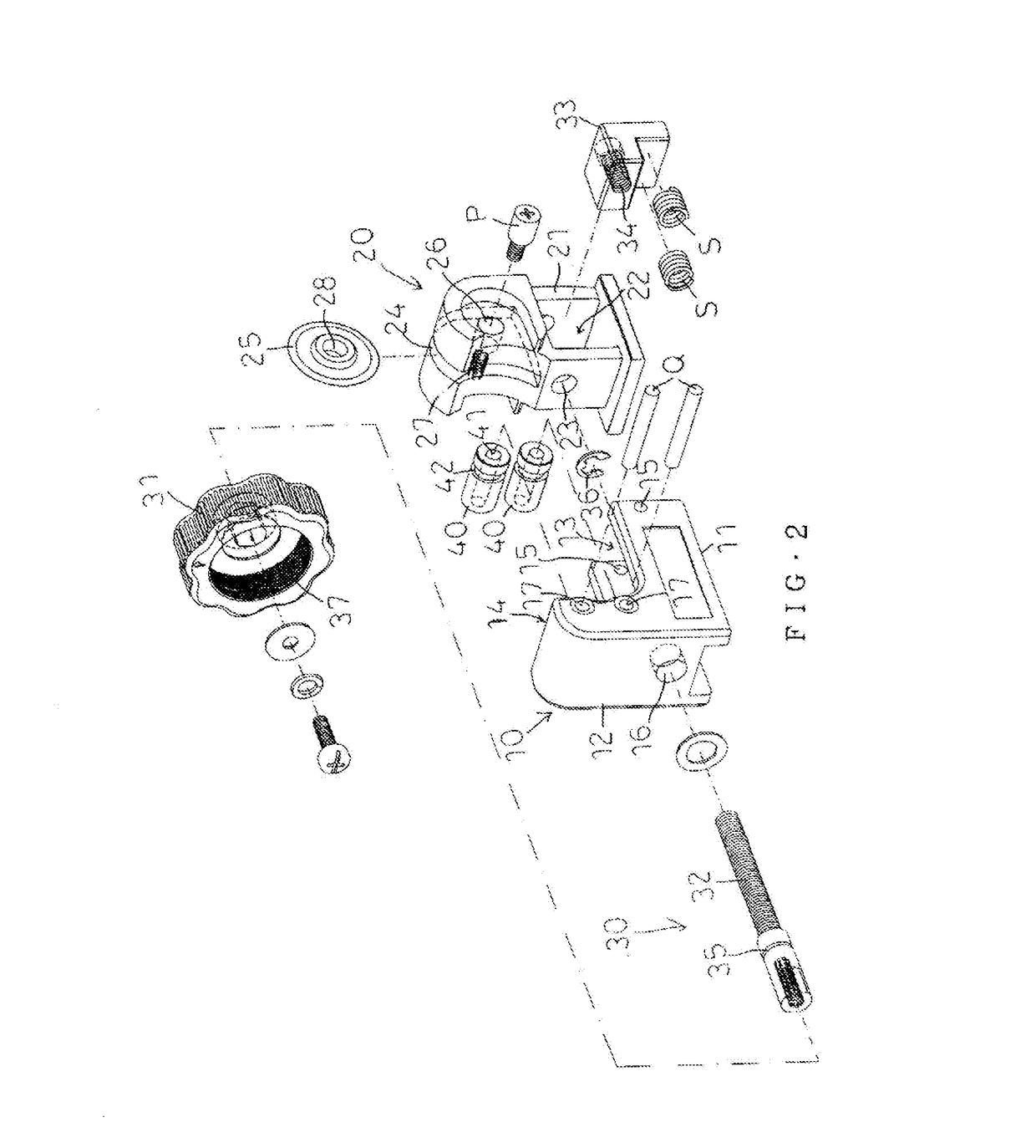
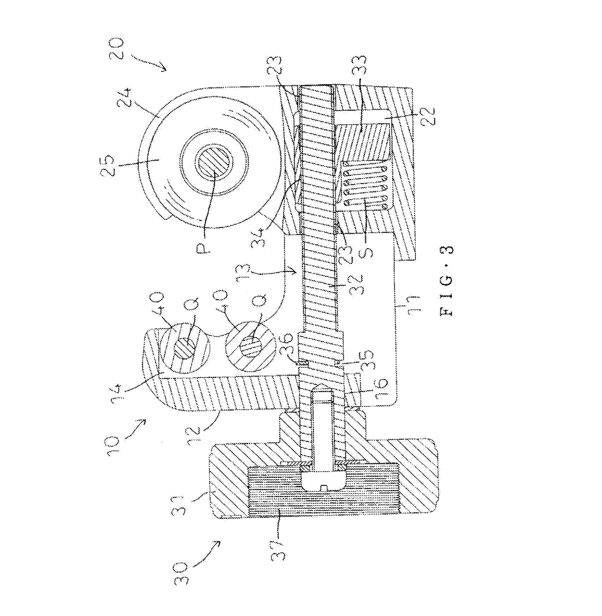
[0023]Referring to the drawings and initially to FIGS. 1-4, a tube cutter in accordance with the preferred embodiment of the present invention comprises a main body 10, a holder 20 slidably mounted on a first side of the main body 10, a slide 33 slidably mounted in the holder 20, a guide bolt 30 rotatably mounted on the main body 10, two rollers 40 pivotally mounted on a second side of the main body 10, and a cutting wheel 25 rotatably mounted on the holder 20 and corresponding to the two rollers 40.

[0024]The main body 10 is provided with a first through hole 16 corresponding to the holder 20 and allowing passage of the guide bolt 30.

[0025]The holder 20 is provided with a receiving space 22 corresponding to the guide bolt 30. The holder 20 is provided with two second through holes 23 located at two sidewalls of the receiving space 22 and aligning with the first through hole 16 of the main body 10. The two second through holes 23 of the holder 20 allow passage of the guide bolt 30.

[0...


PUM

PropertyMeasurementUnit
rotationaaaaaaaaaa
torqueaaaaaaaaaa
energyaaaaaaaaaa

Abstract

A tube cutter includes a main body, a holder slidably mounted on the main body, a guide bolt rotatably mounted on the main body and locked onto a lower portion of the holder to drive and move the holder forward or backward by rotation of the guide bolt, and a driving handle removably mounted on the guide bolt to drive and rotate the guide bolt, and to enhance the torque of the tube cutter.

Description

BACKGROUND OF THE INVENTION1. Field of the Invention[0001]The present invention relates to a cutter and, more particularly, to a tube cutter for cutting a tube.2. Description of the Related Art[0002]A conventional tube cutter comprises a substantially U-shaped main body having a first end provided with a screw hole, a cutting wheel mounted on a second end of the main body, a slide movably mounted on the main body, two rollers mounted on the slide and aligning with the cutting wheel, and a threaded rod screwed through the screw hole of the main body and having a first end resting on the two rollers, and a control knob secured on a second end of the threaded rod. In operation, when the threaded rod is rotated by the control knob, the threaded rod is moved axially relative to the main body to drive the two rollers which drive the slide to move on the main body, so that the two rollers are moved relative to the cutting wheel. Thus, when the tube cutter is mounted on a tube, the two roll...

Claims


Application Information

Patent Timeline
Patent Type & Authority Applications(United States)
IPC IPC(8): B26D3/16
CPCB26D3/169B23D21/00B26D1/14B26D2007/013
Inventor LIAO, YU-ZHU
Owner LIAO BING CHENG
Why Eureka
Try Eureka