Pad package structure for nailer

Active Publication Date: 2007-11-06
YONG SONG HARDWARE & TOOL
View PDF7 Cites 0 Cited by
  • Summary
  • Abstract
  • Description
  • Claims
  • Application Information

AI Technical Summary

Benefits of technology

[0005]The primary objective of the present invention is to provide a pad package structure for a nailer, wherein the package box has a plurality of removable catch plates, so that the pull

Problems solved by technology

However, a user needs to remove the cover from the package box and then to remove the pads from

Method used


Image

  • Pad package structure for nailer
  • Pad package structure for nailer
  • Pad package structure for nailer

Examples


Embodiment Construction

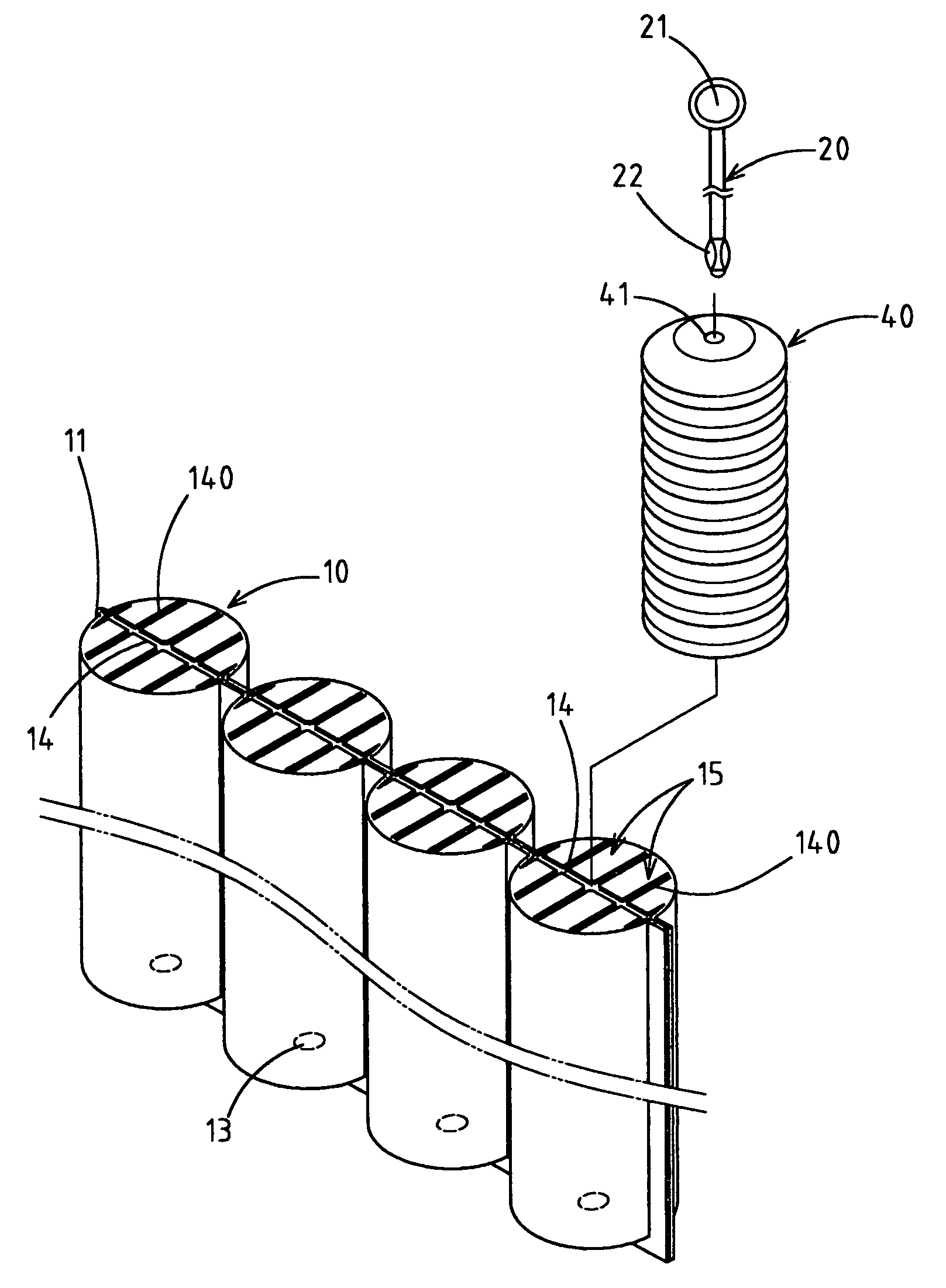
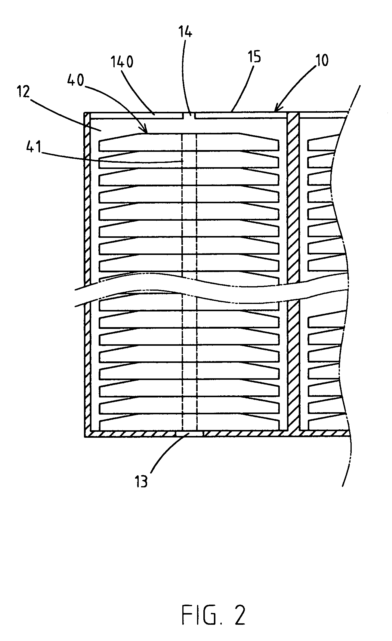
[0022]Referring to the drawings and initially to FIGS. 1-5, a pad package structure for a nailer in accordance with the preferred embodiment of the present invention comprises a plurality of package boxes 10, a plurality of pads 40 mounted in each of the package boxes 10, and a pull bar 20 mounted on each of the package boxes 10 and extended through each of the pads 40 to move the pads 40.

[0023]The package boxes 10 are connected with each other in a serial manner by a plurality of connecting portions 11. Each of the package boxes 10 is substantially cylindrical. Each of the package boxes 10 has an inside formed with a receiving space 12 and has a top formed with a plurality of removable catch plates 15 and a bottom formed with a through hole 13 communicating with the receiving space 12. The top of each of the package boxes 10 has a central portion formed with a central cutout 14 radially extended through the top of each of the package boxes 10. The top of each of the package boxes 1...


PUM


Abstract

A pad package structure for a nailer includes at least one package box having a top formed with a plurality of removable catch plates, a plurality of pads mounted in the package box, and a pull bar mounted on the package box and extended through each of the pads to move the pads. Thus, the package box has a plurality of removable catch plates, so that the pull bar and the pads can be removed from the package box directly by pushing and expanding the catch plates of the package box, thereby facilitating the user operating the pad package structure.

Description

BACKGROUND OF THE INVENTION[0001]1. Field of the Invention[0002]The present invention relates to a pad package structure for a nailer, and more particularly to a pad package structure, wherein the package box has a plurality of removable catch plates, so that the pull bar and the pads can be removed from the package box directly by pushing and expanding the catch plates, thereby facilitating the user operating the pad package structure.[0003]2. Description of the Related Art[0004]A conventional pad package structure for a nailer comprises a package box, a plurality of pads mounted in the package box, and a cover mounted on a top of the package box to cover the pads. In use, the cover is removed from the package box, so that the pads can be removed outward from the package box for use by the nailer. However, a user needs to remove the cover from the package box and then to remove the pads from the package box for use, thereby causing inconvenience to the use when needing to use the p...

Claims


Application Information

Patent Timeline
IPC IPC(8): B65D85/00
CPCB25C5/1693
Inventor CHOU, CHIEN-CHI
Owner YONG SONG HARDWARE & TOOL
Why Eureka
Try Eureka