Antenna and portable terminal using the same

a portable terminal and antenna technology, applied in the field of portable terminals, can solve the problems of loop antenna being unable to establish a communication with the ic card, difficult to read information, etc., and achieve the effects of reducing air field in the communicable area, superior communication performance, and expanding the communicable area

Inactive Publication Date: 2011-09-22
PANASONIC INTELLECTUAL PROPERTY MANAGEMENT CO LTD
View PDF10 Cites 87 Cited by
  • Summary
  • Abstract
  • Description
  • Claims
  • Application Information

AI Technical Summary

Benefits of technology

[0011]The present invention makes it possible to provide an antenna that exhibits superior communication performance within a communicable area because an air field in the communicable area is reduced while expanding the communicable area and provide a portable terminal using the antenna.
[0012]Another objective of the present invention is to cause an electric current oriented in a direction to cancel an electric current flowing through a loop antenna to flow through the notch, whereby an electric current oriented in the same direction as that of the electric current flowing through the loop antenna flows through the entire metallic body, so that the antenna pattern can be

Problems solved by technology

For these reasons, when the loop antenna reads information from; for instance, a non-contact IC card, difficulty is often encountered in reading information.
As a conseq

Method used


Image

  • Antenna and portable terminal using the same
  • Antenna and portable terminal using the same
  • Antenna and portable terminal using the same

Examples


first embodiment

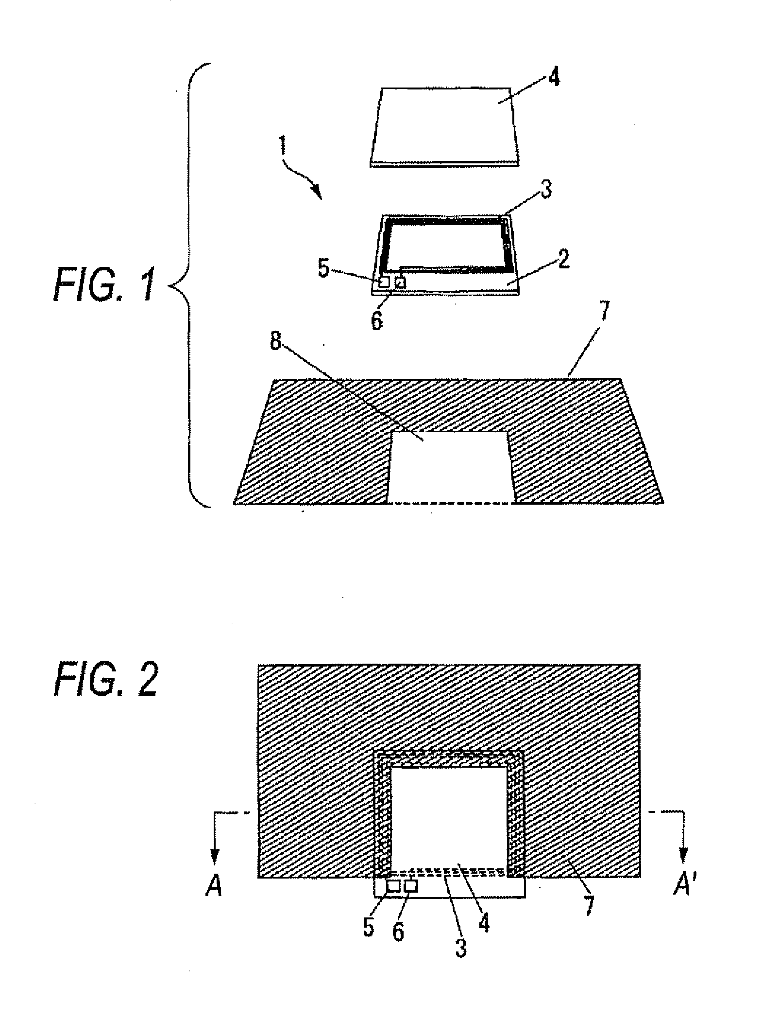
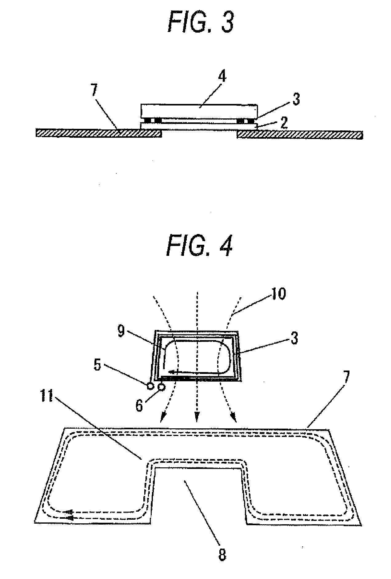
[0037]FIG. 1 is an oblique perspective view of an antenna of a first embodiment of the present invention; FIG. 2 is a top view of the antenna of the first embodiment of the present invention; and FIG. 3 is a side view of the antenna of the first embodiment of the present invention. FIG. 3 is a cross sectional view taken along line A-A′ shown in FIG. 2.

[0038]The antenna 1 shown in FIG. 1 includes a loop antenna pattern 3 laid on an antenna board 2. In FIG. 1, the antenna pattern3 exemplifies a three-turn antenna. However, the antenna pattern is not limited to three turns.

[0039]In order to lessen influence generated when metal is placed on the antenna, a magnetic sheet 4 is placed on the antenna pattern 3.

[0040]The antenna pattern 3 is connected to an input-output terminal of a matching circuit and an input-output terminal of an IC by means of input-output terminals 5 and 6.

[0041]A metallic body 7 is provided with a notch 8 that is formed so as to connect with a periphery of the metal...

second embodiment

[0070]FIG. 8 is an oblique perspective view of the antenna 1 of a second embodiment of the present invention. FIG. 9 is a plan view of the antenna of the second embodiment of the present invention. FIG. 10 is a side view of the antenna of the second embodiment of the present invention.

[0071]In the antenna 1 shown in FIG. 8, the loop-shaped antenna pattern 3 is formed on the antenna board 2. FIG. 8 illustrates a case where the antenna pattern 3 has three turns. However, the number of turns of the antenna pattern is not limited to three. In order to lessen influence generated when metal is placed on the antenna, the magnetic sheet 4 is placed on the antenna pattern 3. The antenna pattern 3 is connected to an input-output terminal of a matching circuit and an input-output terminal of an IC by means of the input-output terminals 5 and 6. The metallic body 7 is positioned substantially in contact with the antenna board. The notch 8 of the metallic body 7 is cut out along the aperture of ...


PUM


Abstract

The present invention aims at providing an antenna that exhibits superior communication performance within a communicable area because an air field within the communicable area is reduced while the communicable area is being expanded, and also providing a portable terminal using the same.
In order to accomplish the objective, the antenna of the present invention includes the followings; namely, a loop antenna having an aperture; a metallic body that opposes the loop antenna and that is electrically insulated from the loop antenna; and a notch that is provided in the metallic body and that is coupled with a periphery of the metallic body, wherein at least a portion of the loop antenna opposes the metallic body, and at least a portion of the notch is covered with the aperture.

Description

BACKGROUND[0001]1. Field of the Invention[0002]The present invention relates to an antenna for use in RF-ID (Radio Frequency Identification) and NFC (Near Field Communication), as well as to a portable terminal using the same.[0003]2. Description of the Related Art[0004]In recent years, a loop antenna has frequently been used in a portable terminal, like a portable phone and a smart phone, in order to read information from a non-contact IC card and an IC tag and exchange information with a reader / writer.[0005]In general, the loop antenna is smaller than the non-contact IC card, and a magnetic field capture area (a communicable area) is narrow. For these reasons, when the loop antenna reads information from; for instance, a non-contact IC card, difficulty is often encountered in reading information.[0006]Accordingly, in order to expand the communicable area, a combination of the loop antenna with a metallic line is available (see; for instance, JP-2008-28506A).[0007]However, since th...

Claims


Application Information

Patent Timeline
IPC IPC(8): H01Q7/00
CPCH01Q1/2225H01Q13/10H01Q7/00H01Q1/243
Inventor HASHIMOTO, YOSHINORI
Owner PANASONIC INTELLECTUAL PROPERTY MANAGEMENT CO LTD
Why Eureka
Try Eureka