Method and apparatus to negotiate channel sharing in PLC network

a technology of channel sharing and apparatus, applied in data switching networks, powerline communications applications, high-level techniques, etc., can solve the problems of inability of respective coordinators of cells to communicate with each other, inability to adapt to the new wiring, and high cost of retrofitting. achieve the effect of enhancing communication performance and eliminating interference between adjacent cells

Inactive Publication Date: 2007-10-04
SAMSUNG ELECTRONICS CO LTD
View PDF5 Cites 64 Cited by
  • Summary
  • Abstract
  • Description
  • Claims
  • Application Information

AI Technical Summary

Benefits of technology

[0013]The present general inventive concept provides a method of negotiating channel sharing between adjacent cells, which interfere with each other, in a power line communication (PLC) network in order to allow the adjacent cells to effectively share a channel through a negotiation process and to prevent the negotiation process itself from interfering with an adjacent cell. Since the adjacent cells can effectively share a channel using the method, interference between the adjacent cells can be eliminated, and communication performance can be enhanced.

Problems solved by technology

Most homes are not equipped with specialized wiring for networking, and retrofitting them with new wiring is very expensive.
When there are a plurality of cells in a power line communication (PLC) network, it is impossible for respective coordinators of the cells to communicate with one another.
However, stations in different cells may interfere with one another.
However, since stations A1 (STA-A1) and B1 (STA-B1), which are respectively included in the cells A and B, can communicate with each other, they interfere with each other.
Consequently, this negotiation process interferes with station B1.
However, if the negotiation attempt of station A1 (STA-A1) is made during the beacon period or CFP of station B1 (STA-B1), the negotiation attempt itself may serve as interference to station B1 (STA-B1).

Method used


Image

  • Method and apparatus to negotiate channel sharing in PLC network
  • Method and apparatus to negotiate channel sharing in PLC network
  • Method and apparatus to negotiate channel sharing in PLC network

Examples


Embodiment Construction

[0037]Reference will now be made in detail to the embodiments of the present general inventive concept, examples of which are illustrated in the accompanying drawings, wherein like reference numerals refer to the like elements throughout. The embodiments are described below in order to explain the present general inventive concept by referring to the figures.

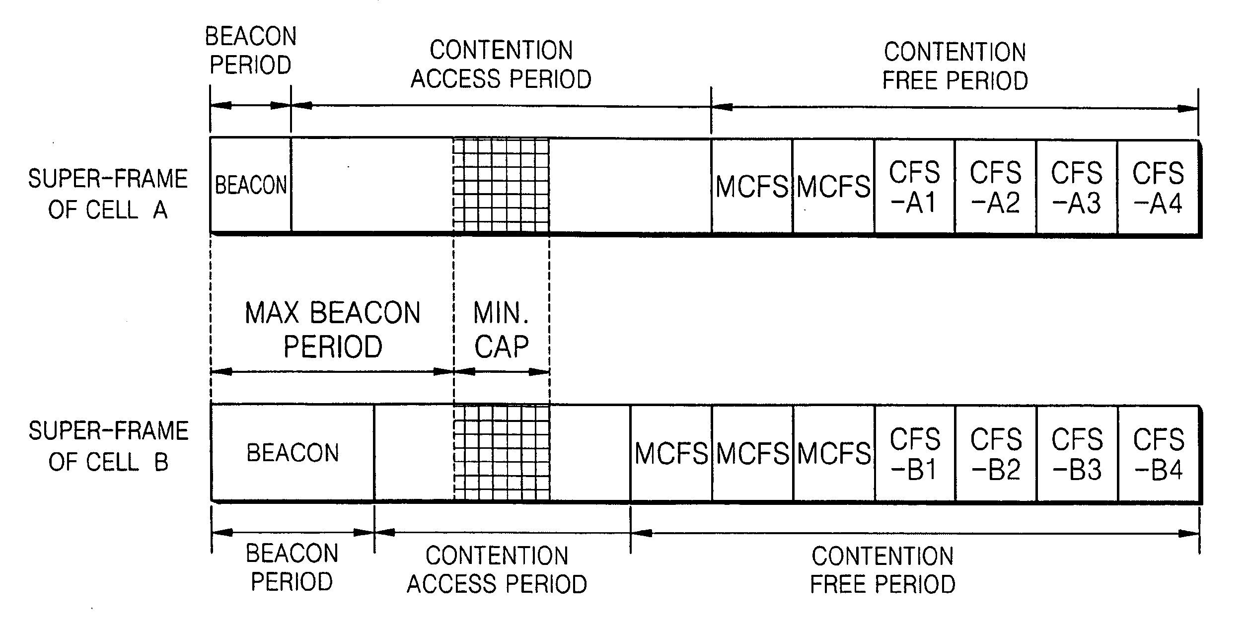
[0038]FIG. 3 illustrates a super-frame structure in a power line communication (PLC) network according to an embodiment of the present general inventive concept. FIG. 3 also illustrates the beacon period, a contention access period (CAP), and a contention free period (CFP) of the super-frame structure of cells A and B. The CAP uses a carrier sense multiple access (CSMA) method, and the CFP uses a time division multiple access (TDMA) method. Time information of the CAP and the CFP is included in a beacon and is transmitted during the beacon period.

[0039]In the present embodiment, a maximum beacon period, which is a virtual period...


PUM


Abstract

A method of negotiating channel sharing between adjacent cells when there are a plurality of cells in a power line communication (PLC) network. The method includes attempting to negotiate the channel sharing during a minimum contention access period (CAP) which starts after a maximum beacon period ends and ends before a CAP of each PLC cell ends, wherein the maximum beacon period indicates a maximum size that a beacon frame in a super-frame transmitted from a coordinator of each PLC cell can have. When an attempt to negotiate the channel sharing is made using this method, interference does not occur during channel sharing negotiation, and effective channel sharing can be achieved, thereby eliminating interference between adjacent cells.

Description

CROSS-REFERENCE TO RELATED APPLICATIONS[0001]This application claims priority under 35 U.S.C. § 119(a) of Korean Patent Application No. 10-2006-0029808, filed on Mar. 31, 2006, and Korean Patent Application No. 10-2006-0067944, filed on Jul. 20, 2006, in the Korean Intellectual Property Office, the disclosure of which is incorporated herein in its entirety by reference.BACKGROUND OF THE INVENTION[0002]1. Field of the Invention[0003]The present general inventive concept relates to a method and apparatus to negotiate channel sharing between adjacent cells when there are a plurality of cells in a power line communication (PLC) network.[0004]2. Description of the Related Art[0005]Recently there has been widespread adoption of digital consumer electronic technologies such as digital TV's, video recorders, and computers, resulting in an increased need for home networking technologies that enable seamless distribution of data and multimedia. Most homes are not equipped with specialized wir...

Claims


Application Information

Patent Timeline
Patent Type & Authority Applications(United States)
IPC IPC(8): H04B7/212
CPCH04B3/542H04B2203/5408H04L12/417H04L12/413H04B2203/5445Y02D30/70
Inventor CHOI, JUN-HAELEE, JOON-HEELEE, JU-HANSUNG, HYUN-AHKIM, IN-HWANYOU, HO-JEONG
Owner SAMSUNG ELECTRONICS CO LTD
Why Eureka
Try Eureka