Antenna steering for an access point based upon control frames

a control frame and access point technology, applied in the field of wireless local area networks, can solve the problems of monopolizing antennas and degrading the quality of communication between the remote station and the access point, and achieve the effects of supporting more users in the network, enhancing the throughput of individual remote stations, and enhancing the service li

Inactive Publication Date: 2009-10-27
IPR LICENSING INC
View PDF47 Cites 64 Cited by
  • Summary
  • Abstract
  • Description
  • Claims
  • Application Information

AI Technical Summary

Benefits of technology

[0009]An improvement over simple diversity is provided through an antenna steering process for access points (i.e., wireless gateways) used in wireless local area networks. Directional antennas improve the throughput of the network, and increase the range between the access point and the remote stations (i.e., wireless user devices). A directional antenna provides a higher signal-to-noise ratio than an omni-directional antenna in most cases, thus allowing the link to operate at higher data rates.
[0011]According to the principles of the present invention, during processes such as registration, authentication or subsequent data exchanges between the access point and a selected remote station, a preferred direction for the steered access point antenna is determined. In one embodiment, software or firmware operating at the access point makes this determination. The access point antenna control software / firmware may build a database that includes the identity of the remote station and the antenna direction associated with that station for achieving optimum communications performance.
[0013]The benefits of augmenting the access point with a directional antenna are two-fold: improved throughput to individual remote stations and an ability to support more users in the network. In most RF environments, the signal level received at the remote station can be improved by having the access point transmit using a shaped antenna beam pointed in the direction of the station. The shaped antenna beam may provide a 3-5 dB gain advantage, for example, over the omni-directional antenna typically deployed with an access point. The increased signal level allows the link between the access point and the remote station to operate at higher data rates, especially at the outer band of the coverage area. The directional antenna steering process is resident in the access point to support operation with the remote stations.

Problems solved by technology

Monopole antennas are susceptible to effects that degrade the quality of communication between the remote station and the access point, such as reflection or diffraction of radio wave signals caused by intervening objects.

Method used


Image

  • Antenna steering for an access point based upon control frames
  • Antenna steering for an access point based upon control frames
  • Antenna steering for an access point based upon control frames

Examples


Embodiment Construction

[0041]The present invention will be described more fully hereinafter with reference to the accompanying drawings, in which preferred embodiments of the invention are shown. This invention may, however, be embodied in many different forms and should not be construed as limited to the embodiments set forth herein; rather, these embodiments are provided so that this disclosure will be thorough and complete, and will fully convey the scope of the invention to those skilled in the art. Like numbers refer to like elements throughout, and prime notation is used to indicate similar elements in alternate embodiments.

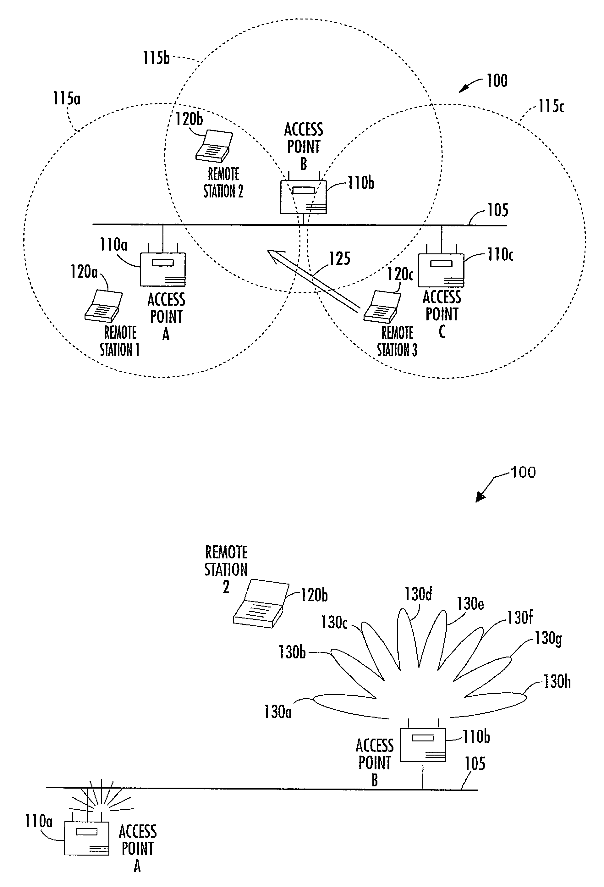
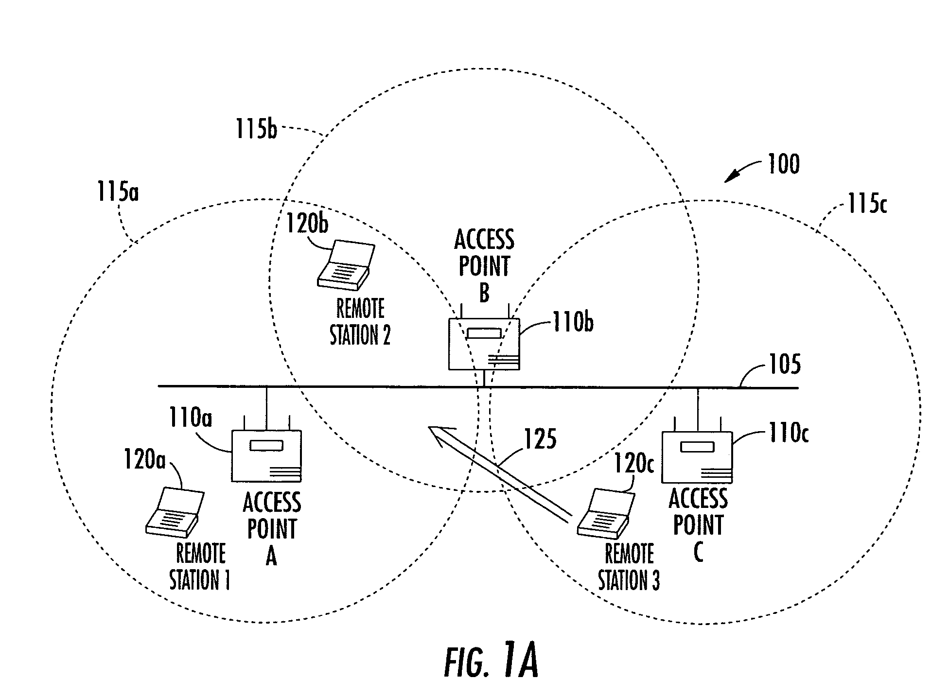
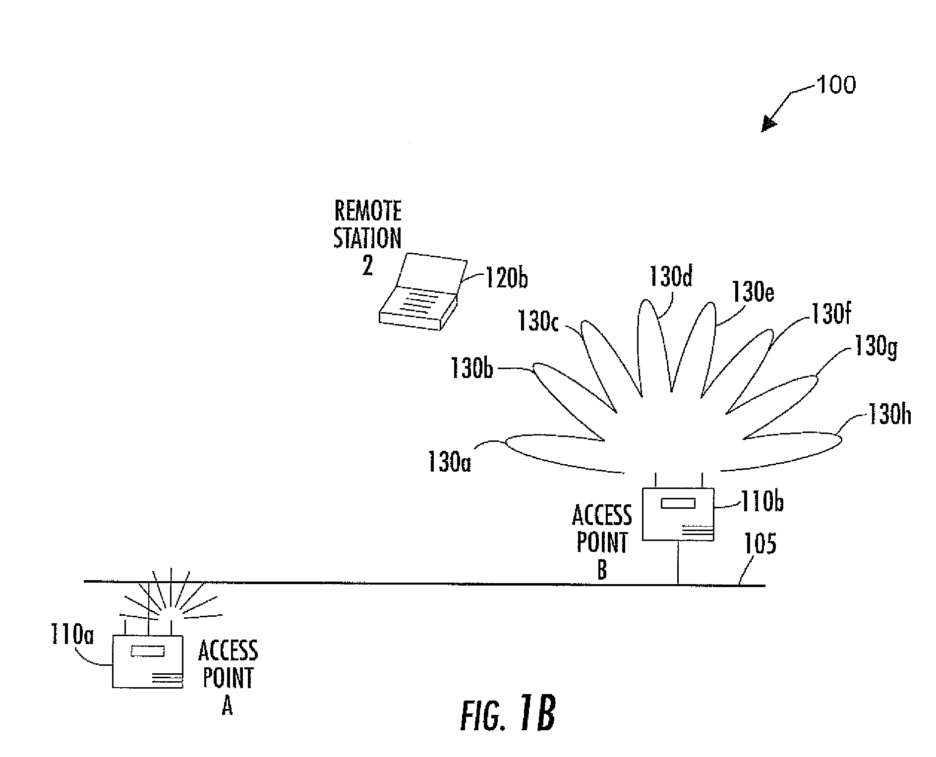
[0042]Referring initially to FIG. 1A, a wireless local area network (WLAN) 100 having a distribution system 105 will initially be discussed. Access points 110a, 110b and 110c are connected to the distribution system 105 via wired connections, such as wired data network connections. Each of the access points 110a, 110b and 110c has a respective zone 115a, 115b, 115c in which it is...


PUM


Abstract

A method for operating an access point in a wireless local area network (WLAN) is provided. The access point includes a directional antenna for communicating with at least one remote station in a forward link based upon an exchange of packet data comprising a plurality of control frames and a data frame. The directional antenna includes a plurality of antenna patterns. The method includes receiving a first control frame via a first antenna pattern of the directional antenna from the remote station, transmitting a first data frame to the remote station, and receiving a second control frame via a second antenna pattern of the directional antenna from the remote station. A signal quality of the first control frame received via the first antenna pattern and a signal quality of the second control frame received via the second antenna pattern are measured. The respective measured signal qualities associated with the first and second antenna patterns are compared.

Description

RELATED APPLICATION[0001]This application claims the benefit of U.S. provisional application Ser. No. 60 / 479,701, filed Jun. 19, 2003, the entire contents of which are incorporated herein by reference.FIELD OF THE INVENTION[0002]The present invention relates to the field of wireless local area networks, and in particular, to an antenna steering algorithm for an access point operating within a wireless local area network.BACKGROUND OF THE INVENTION[0003]Various standards allow remote stations, such as portable computers, to be moved within a wireless local area network (WLAN) and connect via radio frequency (RF) transmissions to an access point (AP) that is connected to a wired network. The wired network is often referred to as a distribution system. The various standards include the IEEE 802.11 standard and its corresponding letter revisions thereof, such as 802.11b and 802.11g, for example.[0004]A physical layer in the remote stations and in the access point provides low level tran...

Claims


Application Information

Patent Timeline
Patent Type & Authority Patents(United States)
IPC IPC(8): H04B7/216H04B7/04H04B7/06H04W88/08
CPCH04B7/0408H04B7/0602H04W88/08H04B7/0608H01Q3/26H01Q21/28
Inventor HOFFMANN, JOHN E.JOHNSON, KEVIN P.NELSON, JR., GEORGE RODNEYREGNIER, JOHN A.
Owner IPR LICENSING INC
Why Eureka
Try Eureka