Image processing apparatus and method of controlling the same

a technology of image processing and apparatus, applied in the field of image correction technique, can solve problems such as image quality degradation

Inactive Publication Date: 2011-09-29
CANON KK
View PDF14 Cites 5 Cited by
  • Summary
  • Abstract
  • Description
  • Claims
  • Application Information

AI Technical Summary

Benefits of technology

[0008]The present invention has been made in consideration of the problems of the prior arts. The present invention provides for the correction of image quality degradation in a captured image caused by aberrations, due to the optical system, and in consideration of the correction limit.

Problems solved by technology

Some recent image capturing apparatuses correct the influence of aberrations by image processing because the use of a multi-pixel image sensor or an optical system with a wide angle or a high zoom ratio makes image quality degradation, caused by the aberrations, apparent.
That is, since the aberration correction amount is limited by the capacity of the storage area, the correction needs to be applied in consideration of the correction limit.

Method used


Image

  • Image processing apparatus and method of controlling the same
  • Image processing apparatus and method of controlling the same
  • Image processing apparatus and method of controlling the same

Examples


first embodiment

[0028]An embodiment of the present invention will now be described in detail with reference to the accompanying drawings. Note that in the following embodiment, an example will be described in which the present invention is applied to a digital camera that is an image processing apparatus and can correct chromatic aberration due to magnification or distortion aberration generated in a captured image due to the optical system. However, the present invention is applicable to a device capable of correcting image quality degradation caused in an input image by the aberrations of the optical system that captured the image.

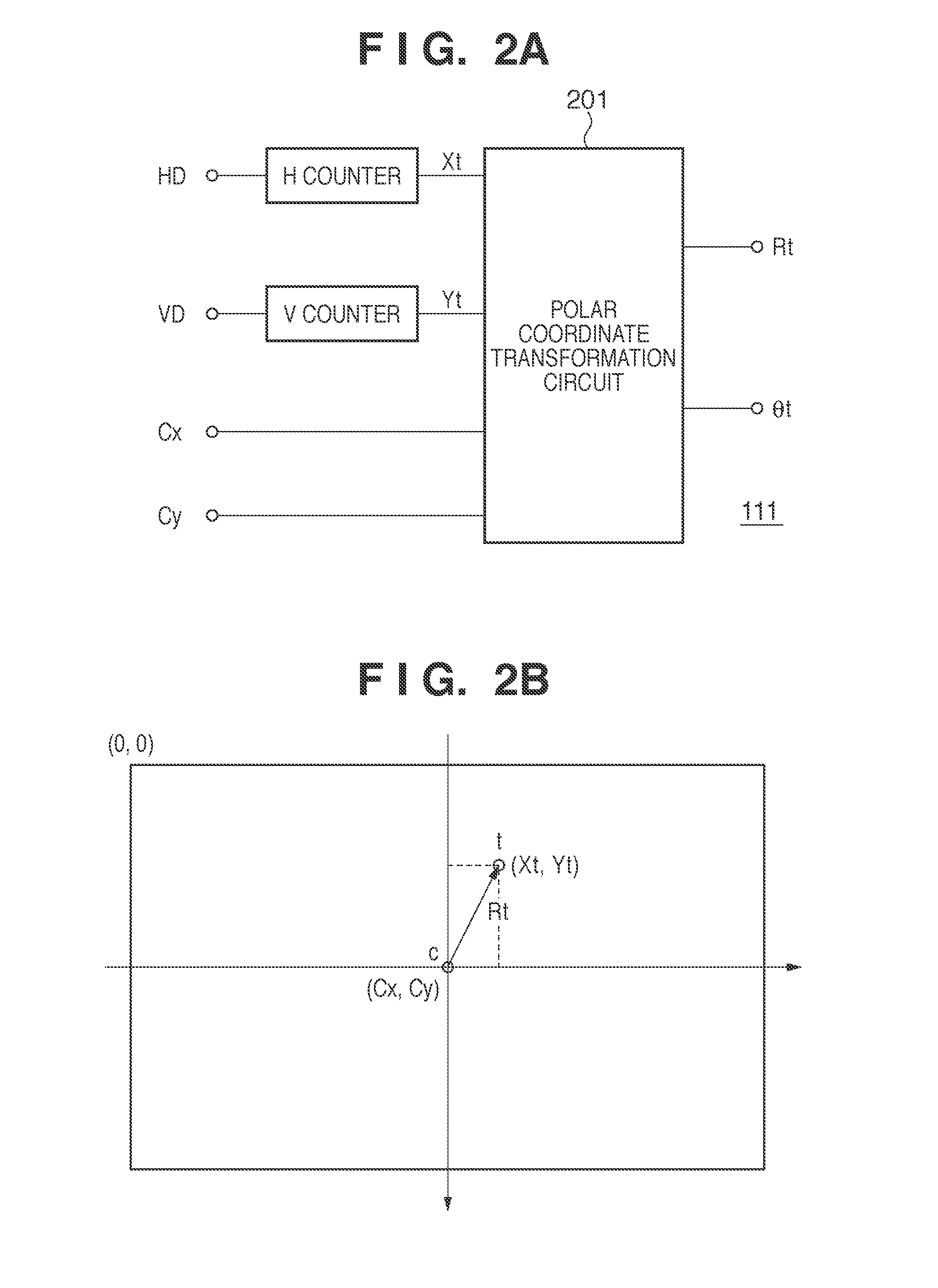
[0029]Note that in this embodiment, the correction amount of the chromatic aberration due to magnification of each of RGB or the distortion aberration will be described below because the aberration correction amount depends on the image height, although the relationship between the correction amount and the image height is different between the chromatic aberration due ...

second embodiment

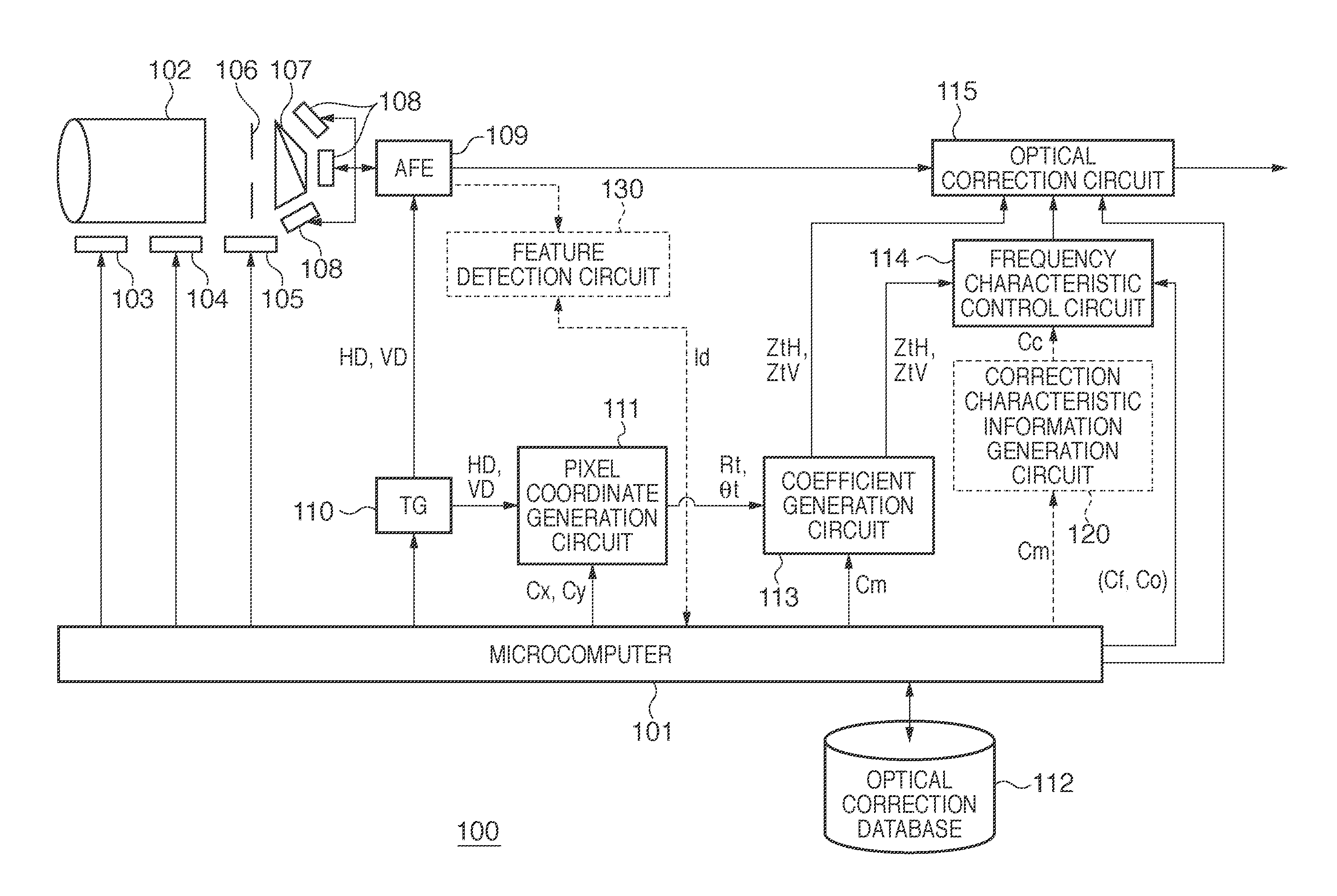
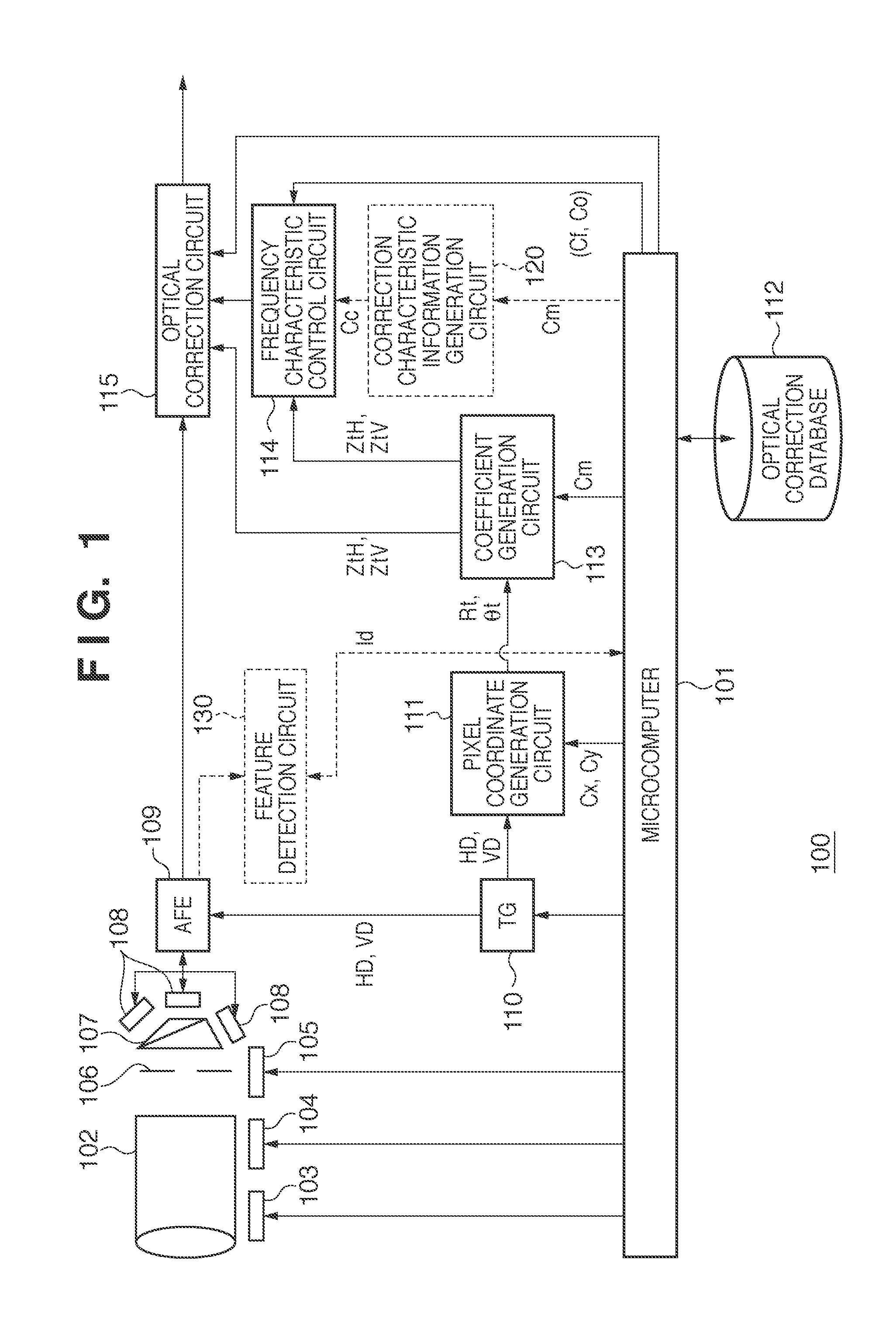
[0078]In this embodiment, aberration correction processing considering the MTF (Modulation Transfer Function) information of the optical system, which represents the perceived resolution of a captured image, will be described in addition to the above-described first embodiment. Note that the functional arrangement of the digital camera of this embodiment is the same as in the first embodiment. The MTF information of an optical system 102 of a digital camera 100 is stored in an optical correction database 112 and read out in a process of correction processing.

[0079]Note that in the above-described first embodiment, an aberration correction amount is calculated based on the approximate function of the correction amount and image height derived by the coefficient generation circuit 113. In the second embodiment, however, a description will be made assuming that the correction amount limit value (first upper limit value) is predetermined by the capacity of a buffer memory 1003 in an opt...

third embodiment

[0085]This embodiment considers correction characteristic information Cc qualitatively representing what sort of impression will be given by corrected image quality when the approximate function of the correction amount and image height is limited by the correction amount limit value determined by the capacity of a buffer memory 1003, as in the second embodiment, in addition to the arrangement of the first embodiment. The correction characteristic information Cc is determined by degrees Ccw and Cch of impression received from corrected image quality based on information Lw of the range of image heights more than the correction amount limit value and a minimum image height Lh in the image height range when the approximate function of the correction amount and image height is limited.

[0086]As for the functional arrangement of a digital camera 100 of this embodiment, a correction characteristic information generation circuit 120 configured to calculate the correction characteristic inf...


PUM


Abstract

The correction amount of an aberration caused in each pixel of the region by the optical system is calculated. A predetermined number of peripheral pixels center on a position apart from the pixel by the distance corresponding to the calculated aberration correction amount are multiplied by interpolation coefficients obtained from an interpolation function and added, thereby deriving the pixel value at the pixel position after correction. If the predetermined number of peripheral pixels around the position apart by the distance corresponding to the calculated aberration correction amount are not present in the readout region, aberration correction is implemented by changing the interpolation function. More specifically, the interpolation function is changed so as to make the frequency response behavior of the interpolation function more moderate than that of the interpolation function that gives the interpolation coefficients to multiply the predetermined number of peripheral pixels and used in the correction processing.

Description

BACKGROUND OF THE INVENTION[0001]1. Field of the Invention[0002]The present invention relates to an image correction technique and, more particularly, to a technique of correcting image degradation caused by aberrations in an optical system used to capture an image.[0003]2. Description of the Related Art[0004]An image captured by an image capturing apparatus such as a digital camera is influenced by the chromatic aberration due to magnification and distortion aberration due to an optical system such as an imaging lens. Focusing on the pixels of the captured image reveals that an image that should be formed on a pixel of interest, in an aberration-free system, is moved, by the aberrations, and formed on the line that connects the pixel of interest and the center of the image.[0005]Some recent image capturing apparatuses correct the influence of aberrations by image processing because the use of a multi-pixel image sensor or an optical system with a wide angle or a high zoom ratio mak...

Claims


Application Information

Patent Timeline
Patent Type & Authority Applications(United States)
IPC IPC(8): H04N5/228H04N5/76
CPCG06T5/006G06T5/001H04N9/045H04N5/3572H04N25/615H04N23/843H04N25/6153H04N1/40G06T3/00H04N25/60H04N23/12
Inventor TERASAWA, KEN
Owner CANON KK
Why Eureka
Try Eureka