
Dental drill extension

a dental drill and extension technology, applied in the field of dental surgery, can solve the problems of increasing the overall length of the drill, obstructing the head of the adjacent teeth,

Inactive Publication Date: 2011-09-29
KLAD CORP
View PDF12 Cites 17 Cited by
  • Summary
  • Abstract
  • Description
  • Claims
  • Application Information

AI Technical Summary

Problems solved by technology

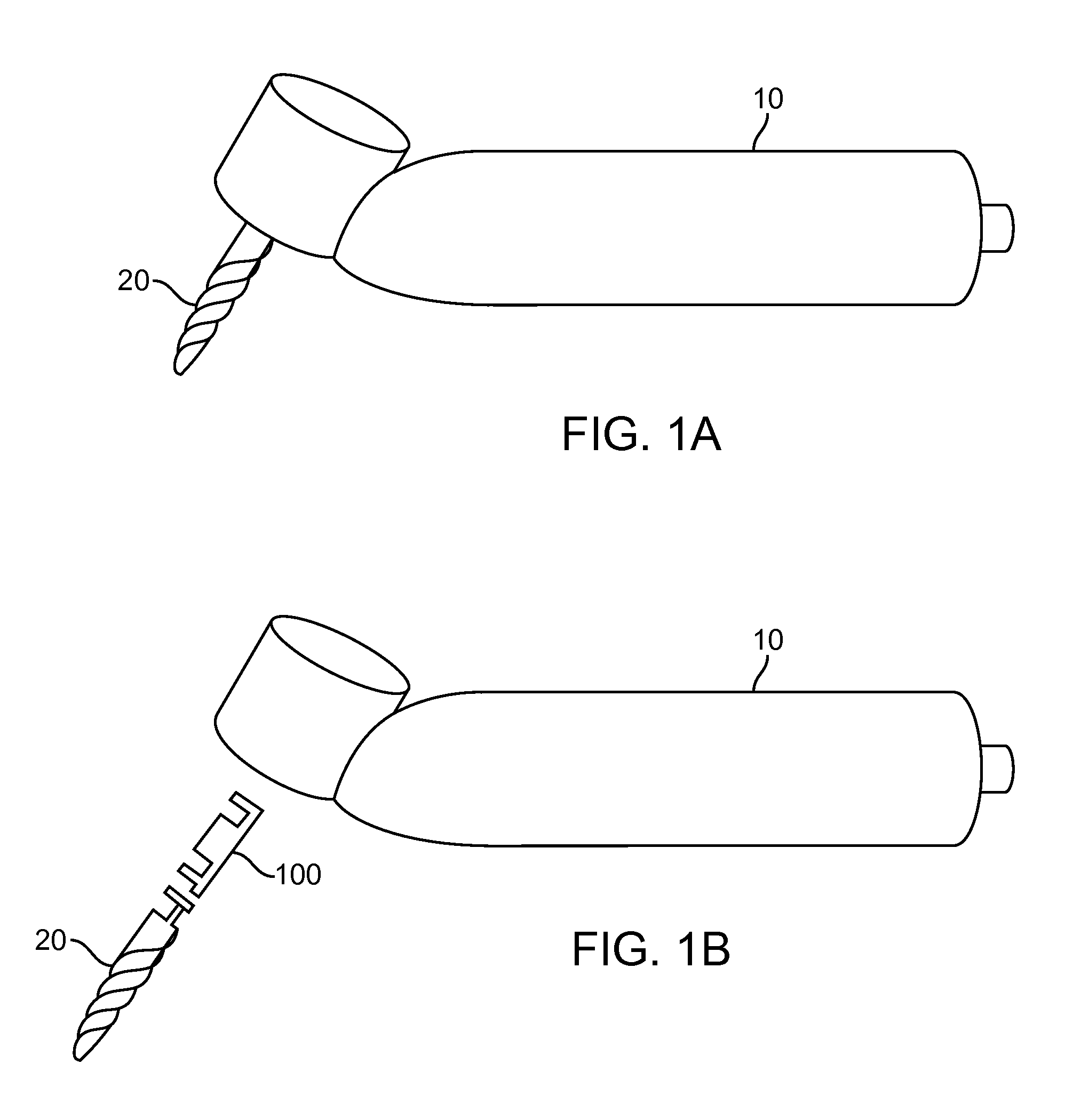
On occasion, adjacent teeth may obstruct the head of the contra angle hand piece from properly accessing and drilling an opening of appropriate depth.
However, the use of these extensions increases the overall length of the drill and can compromise accessing the appropriate location for drilling.

Method used


Image

  • Dental drill extension
  • Dental drill extension
  • Dental drill extension

Examples


Embodiment Construction

[0020]Although the detailed description contains many specifics, these should not be construed as limiting the scope of the invention but merely as illustrating different examples and aspects of the invention. It should be appreciated that the scope of the invention includes other embodiments not discussed in herein. Various other modifications, changes and variations which will be apparent to those skilled in the art may be made in the arrangement, operation and details of the method and apparatus of the present invention disclosed herein without departing from the spirit and scope of the invention as described here.

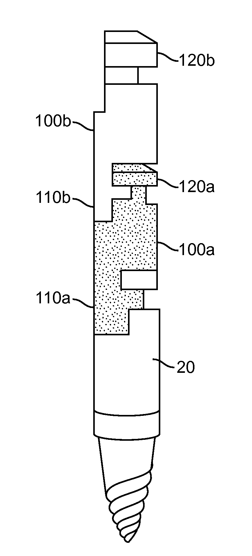
[0021]When performing dentistry, it is often necessary for the operator to create and / or enlarge an opening within a patient's mouth. For example, an implant will require osteotomy to have a specific osteotomy depth determined by the manufacturer of the implant. Thus, it is first necessary to create an opening for the dental implant using a drill, such as a pilot drill....


PUM


Abstract

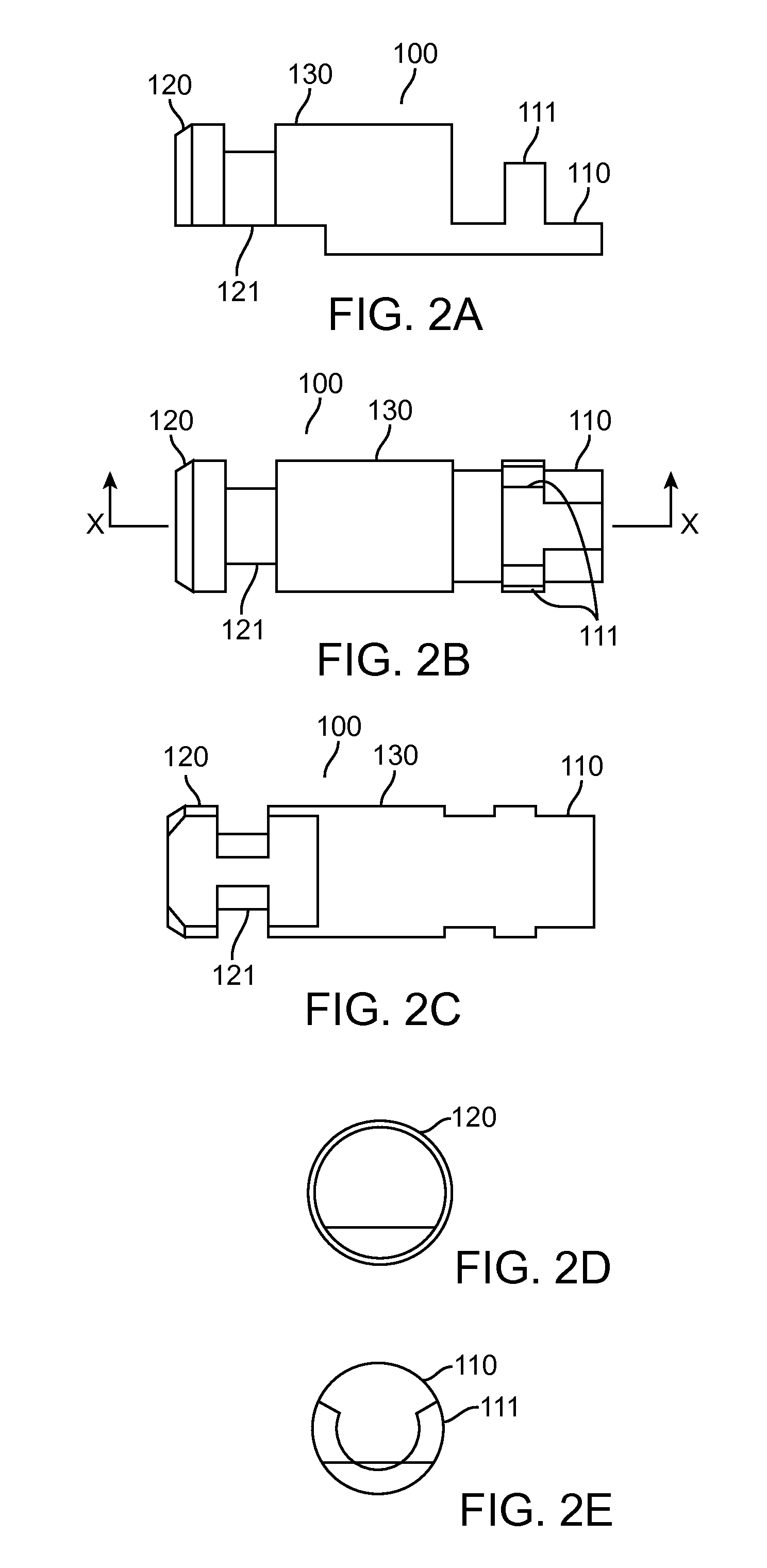
An extender for a dental apparatus comprises a distal connecting portion, a proximal connecting portion, and an elongated portion disposed between the distal connecting portion and the proximal connecting portion, wherein the distal connecting portion is configured to connect to a dental drill bit or the proximal connecting portion and wherein the proximal connecting portion is configured to connect to a dental hand piece or the distal connecting portion.

Description

CROSS-REFERENCES TO RELATED APPLICATIONS[0001]This application claims the benefit of priority under U.S.C. §119(e) of U.S. Provisional Application No. 61 / 340,997, filed on Mar. 25, 2010, the full disclosure of which is incorporated herein by reference.TECHNICAL FIELD[0002]This invention relates generally to the field of dentistry, and more particularly, but not exclusively to extending a dental drill used for procedures such as dental implant.BACKGROUND[0003]Dental implants are an increasingly popular dental restoration option for patients with missing teeth due to excessive decay to the tooth roots, bone or gum damage, or accidents causing physical displacement. Particularly, dental implants may provide a more permanent solution than other procedures such as a crown or a bridge supported by natural tooth roots. Furthermore, dental implants provide an alternative to dentures because they look natural and require less maintenance. Implants further provide a stronger biting surface an...

Claims


Application Information

Patent Timeline
IPC IPC(8): A61C3/02A61C17/02
CPCA61C3/02
Inventor SHIMOO, YOSHIAKI
Owner KLAD CORP
Learn More