Sheet transport apparatus

Active Publication Date: 2011-09-29
KOMORI CORP
View PDF7 Cites 5 Cited by
  • Summary
  • Abstract
  • Description
  • Claims
  • Application Information

AI Technical Summary

Benefits of technology

[0046]According to the features of the preset invention, two-stage allocating delivery in collect folding can be performed, and an increase in productivity, prolongation of the life cycle of a consumable part, a decrease in the running cost, a lighter burden on the operator's work, and a reduction in spending on plants and equipment can be achieved effectively.
[0047]That is, two-stage allocating delivery in collect folding equalizes the mechanical states in the two stages, facilitates agreement between the states in the two stages, and results in

Problems solved by technology

In order to prevent these disadvantages, moreover, a wasteful operation, such as replacement for both of the two stages at the time of one-stage replacement, is performed.
Thus, there have been problems, such as decreased productivity, shortened

Method used


Image

  • Sheet transport apparatus
  • Sheet transport apparatus
  • Sheet transport apparatus

Examples


embodiment 1

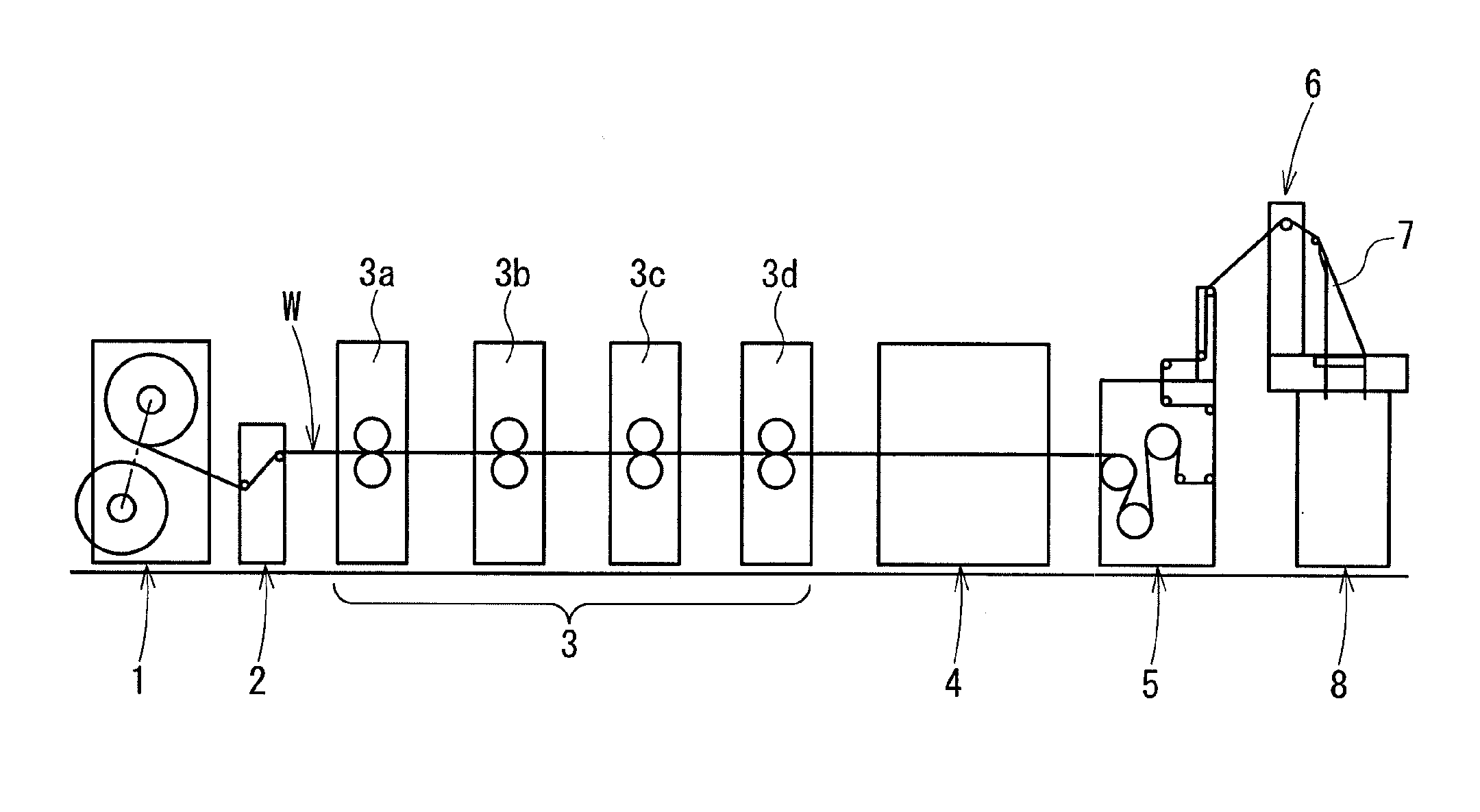
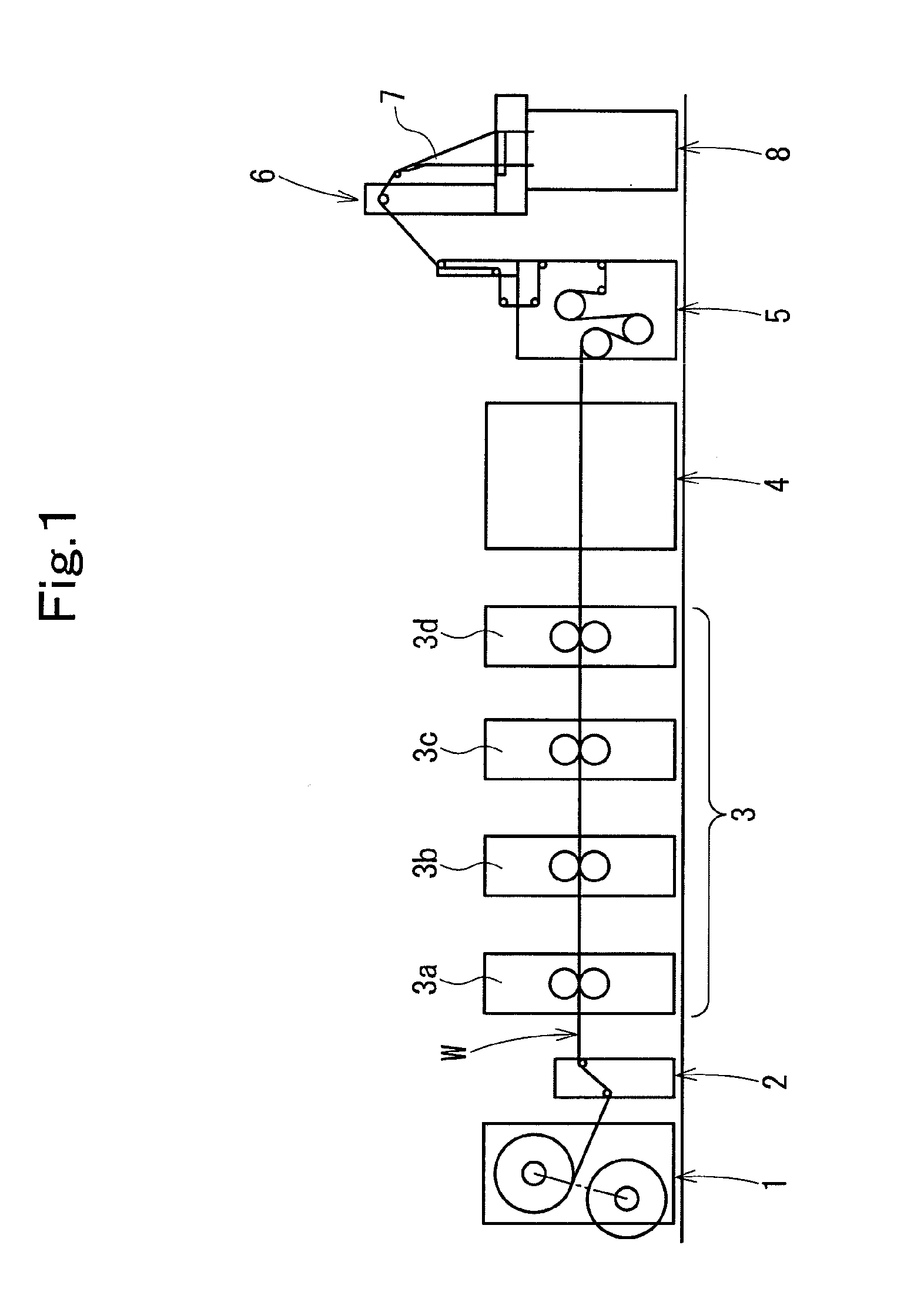
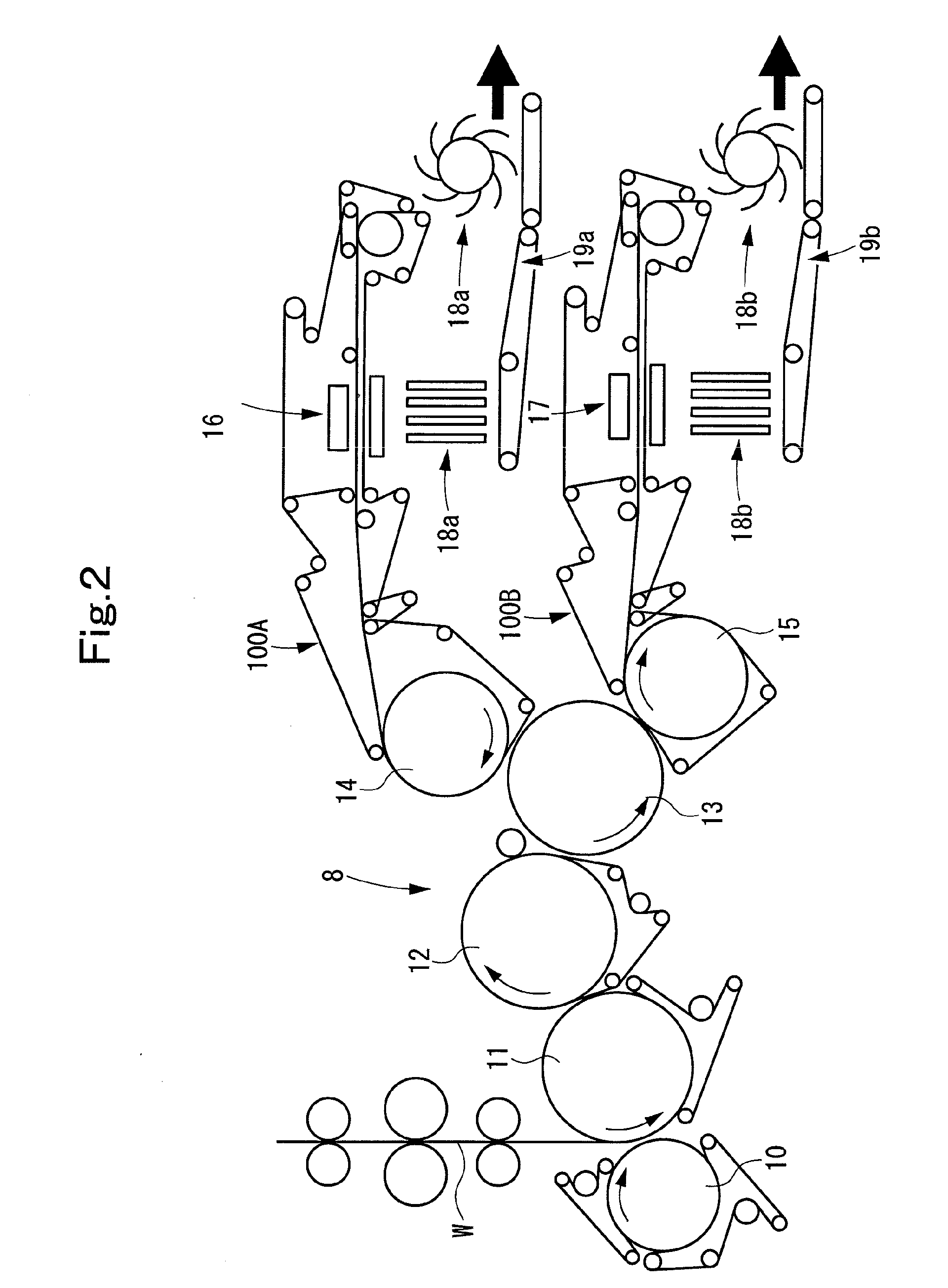
[0130]FIG. 1 is a schematic configurational drawing of a web rotary printing press showing Embodiment 1 of the present invention. FIG. 2 is a schematic configurational drawing of a transport path of a folder. FIG. 3 is a front view of the cylinder arrangement of the folder. FIGS. 4A and 4B are explanation drawings of a collecting and cutting cylinder. FIGS. 5A and 5B are explanation drawings of a folding cylinder. FIGS. 6A and 6B are explanation drawings of a jaw cylinder. FIGS. 7A and 7B are explanation drawings of a reduction cylinder. FIGS. 8A and 8B are explanation drawings of an upper transfer cylinder. FIGS. 9A and 9B are explanation drawings of a lower transfer cylinder.

[0131]FIGS. 10A and 10B are explanation drawings of a pin cam of the collecting and cutting cylinder. FIG. 11 is an explanation drawing of a sucker blade cam of the folding cylinder. FIG. 12 is an explanation drawing of a pin main cam of the folding cylinder. FIGS. 13A and 13B are explanation drawings of a pin...

embodiment 2

[0228]FIG. 27 is a schematic configurational drawing of a transport path of a folder in a web rotary printing press showing Embodiment 2 of the present invention. FIG. 28 is a structural drawing of a cam mechanism. FIGS. 29(a) to 29(d) are explanation drawings of cams. FIG. 30 is an explanation drawing of motions during upper-lower two-stage delivery in non-collect folding. FIG. 31 is an explanation drawing of motions during upper one-stage delivery (merge delivery) in non-collect folding. FIG. 32 is an explanation drawing of motions during upper one-stage delivery (merge delivery) in collect folding. FIG. 33 is an explanation drawing of motions during upper-lower two-stage delivery in collect folding.

[0229]FIG. 34 is an extraction drawing of a first main cam and a second sub-cam during upper-lower two-stage delivery and upper one-stage delivery in non-collect folding and during upper one-stage delivery in collect folding. FIG. 35 is an extraction drawing of the first main cam and t...


PUM

PropertyMeasurementUnit
Diameteraaaaaaaaaa

Abstract

For effective achievement of an increase in productivity, prolongation of the life cycle of a consumable part, a decrease in the running cost, a lighter burden on the operator's work, and a reduction in spending on plants and equipment, a sheet transport apparatus comprises: a folding cylinder (11) for transporting sheets one by one or as a stack of a plurality of the sheets; a jaw cylinder (12) or a reduction cylinder (13) for holding the sheets by alternate ones of holding means and transporting the sheets when the sheets are transported as the stack of the plurality of sheets; an upper transfer cylinder (14) opposing the jaw cylinder or the reduction cylinder; a lower transfer cylinder (15) opposing the jaw cylinder or the reduction cylinder; and switching means for transporting the sheets from the jaw cylinder or the reduction cylinder to the upper transfer cylinder and the lower transfer cylinder, while allocating the sheets to the upper transfer cylinder and the lower transfer cylinder, when the sheets are transported as the stack of the plurality of sheets.

Description

TECHNICAL FIELD[0001]This invention relates to a sheet transport apparatus in a folder or the like of a web rotary printing press.BACKGROUND ART[0002]In a folder of a web rotary printing press, it is common practice to switch folding specifications such as folding in a collect run mode or collect folding (folding in a gathered or stacked state), or folding in a non-collect run mode or non-collect folding (folding in an ungathered or unstacked state), or to switch transport paths during non-collect folding, as in parallel folding two-stage delivery (upper-lower two-stage delivery) or parallel folding merge delivery (upper one-stage delivery) (see Patent Document 1, etc.).[0003]Patent Document 1: JP-A-2002-60128DISCLOSURE OF THE INVENTIONProblems to be solved by the invention[0004]During the above-mentioned collect folding, however, it has been general practice to adopt a manner of delivery, such as delivery in only one stage of two-stage delivery.[0005]If only one stage delivery is p...

Claims


Application Information

Patent Timeline
IPC IPC(8): B31F1/10
CPCB65H45/28B65H45/168
Inventor KOJIMA, NORIYUKIKURIHARA, SHIGEAKITSURUNAGA, HIDENOBU
Owner KOMORI CORP
Why Eureka
Try Eureka