Method and apparatus for channel sounding in an orthogonal frequency division multiplexing communication system

a communication system and orthogonal frequency division technology, applied in the direction of digital transmission, secret communication, sub-channel allocation of transmission paths, etc., can solve the problem that no mechanism has been proposed for the implementation of a trigger-based srs

Active Publication Date: 2011-10-06
GOOGLE TECH HLDG LLC
View PDF7 Cites 80 Cited by
  • Summary
  • Abstract
  • Description
  • Claims
  • Application Information

AI Technical Summary

Problems solved by technology

However, no mechanism has been proposed f

Method used


Image

  • Method and apparatus for channel sounding in an orthogonal frequency division multiplexing communication system
  • Method and apparatus for channel sounding in an orthogonal frequency division multiplexing communication system
  • Method and apparatus for channel sounding in an orthogonal frequency division multiplexing communication system

Examples


Embodiment Construction

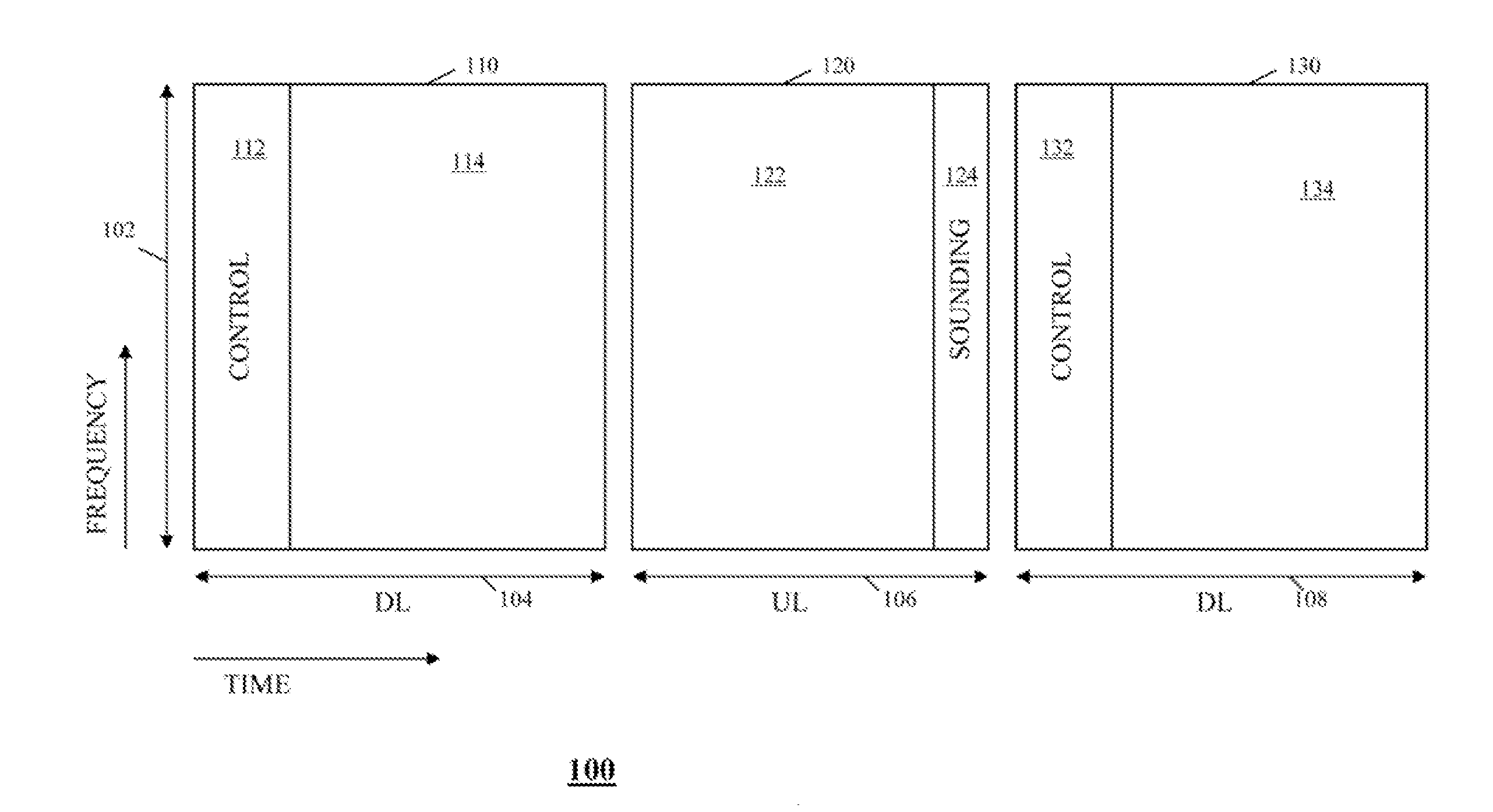
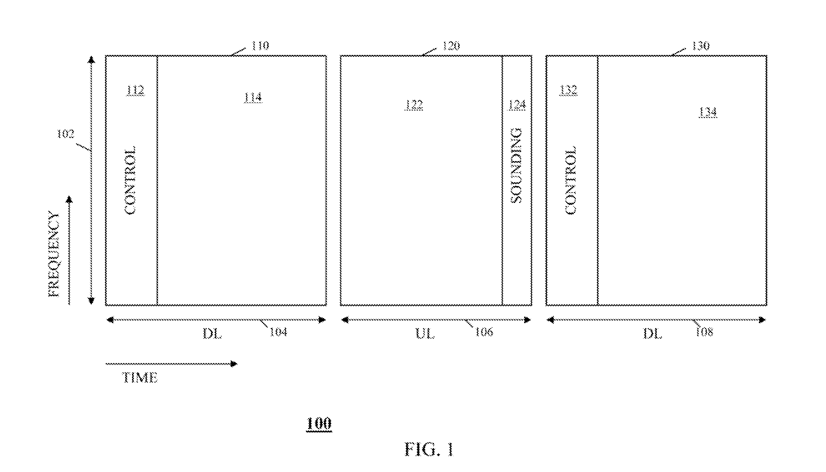
To address the need for a method and an apparatus for implementing a trigger-based SRS in an Orthogonal Frequency Division Multiple Access (OFDMA) communication system, an Orthogonal Frequency Division Multiplexing (OFDM) communication system is provided that triggers a transmission of an uplink sounding signal by use of a Downlink Control Information (DCI) message. In various embodiments of the invention, the DCI message may be used to individually trigger an uplink sounding signal by a single user equipment (UE) or may be used to trigger an uplink sounding signal by a group of users equipment (UEs). The present invention and the following description apply to UEs sounding with one or multiple transmit antennas. The methods that are described henceforth for sounding using a single transmit antenna are assumed to be naturally extendable to multiple transmit antennas by someone skilled in the art. This includes methods where the sounding procedure is set up for transmit antenna-0 and...


PUM


Abstract

An Orthogonal Frequency Division Multiplexing communication system is provided that triggers a transmission of an uplink sounding signal by use of a Downlink Control Information (DCI) message. In various embodiments of the invention, the DCI message may be used to individually trigger an uplink sounding signal by a single user equipment or may be used to trigger an uplink sounding signal by a group of users equipment.

Description

FIELD OF THE INVENTIONThe present invention relates generally to Orthogonal Frequency Division Multiplexing (OFDM) communication systems, and, in particular, to an exchange of channel response information in an OFDM communication system.BACKGROUND OF THE INVENTIONThe Third Generation Partnership Project (3GPP) Long Term Evolution (LTE) standards propose using an Orthogonal Frequency Division Multiple Access (OFDMA) for transmission of data over an air interface. In an OFDMA communication system, a frequency bandwidth is split into multiple contiguous frequency sub-carriers, wherein groups of sub-carriers are arranged in logical frequency resource blocks (not necessarily contiguous in frequency), each resource block comprising multiple orthogonal frequency sub-carriers, that are transmitted simultaneously. A user may then be assigned one or more of the frequency resource blocks for an exchange of user information, thereby permitting multiple users to transmit simultaneously on the di...

Claims


Application Information

Patent Timeline
IPC IPC(8): H04K1/10
CPCH04L27/261H04L5/003
Inventor RATASUK, RAPEEPATGHOSH, AMITABHAMONDAL, BISHWARUP
Owner GOOGLE TECH HLDG LLC
Why Eureka
Try Eureka