Lever connector

a technology of lever connector and lever, which is applied in the direction of coupling device connection, coupling parts engagement/disengagement, electrical apparatus, etc., and can solve problems such as lever turning may be broken

Inactive Publication Date: 2011-10-13
HITACHI METALS LTD
View PDF2 Cites 16 Cited by
  • Summary
  • Abstract
  • Description
  • Claims
  • Application Information

AI Technical Summary

Benefits of technology

[0041]According to one embodiment of the invention, a lever connector is provided with a connecting member manipulating mechanism that includes a contact holding means for maintaining the pressing force applied to each contact, to maintain the electrical connections between the first connecting terminals and the second connecting terminals even when the turn lever is broken. This allows the electrical conduction through the contacts to be secured even when the turn lever is broken. Thus, by applying the lever connector to a hybrid vehicle or electric vehicle, even when the turn lever is broken, the interruption of the electrical conduction through the contacts can be prevented that renders the vehicle impossible to move.

Problems solved by technology

Therefore, the turn lever may be broken when another member strikes against the lever connector.

Method used


Image

  • Lever connector
  • Lever connector
  • Lever connector

Examples


Embodiment Construction

[0064]Below is described a preferred embodiment according to the invention, referring to the accompanying drawings.

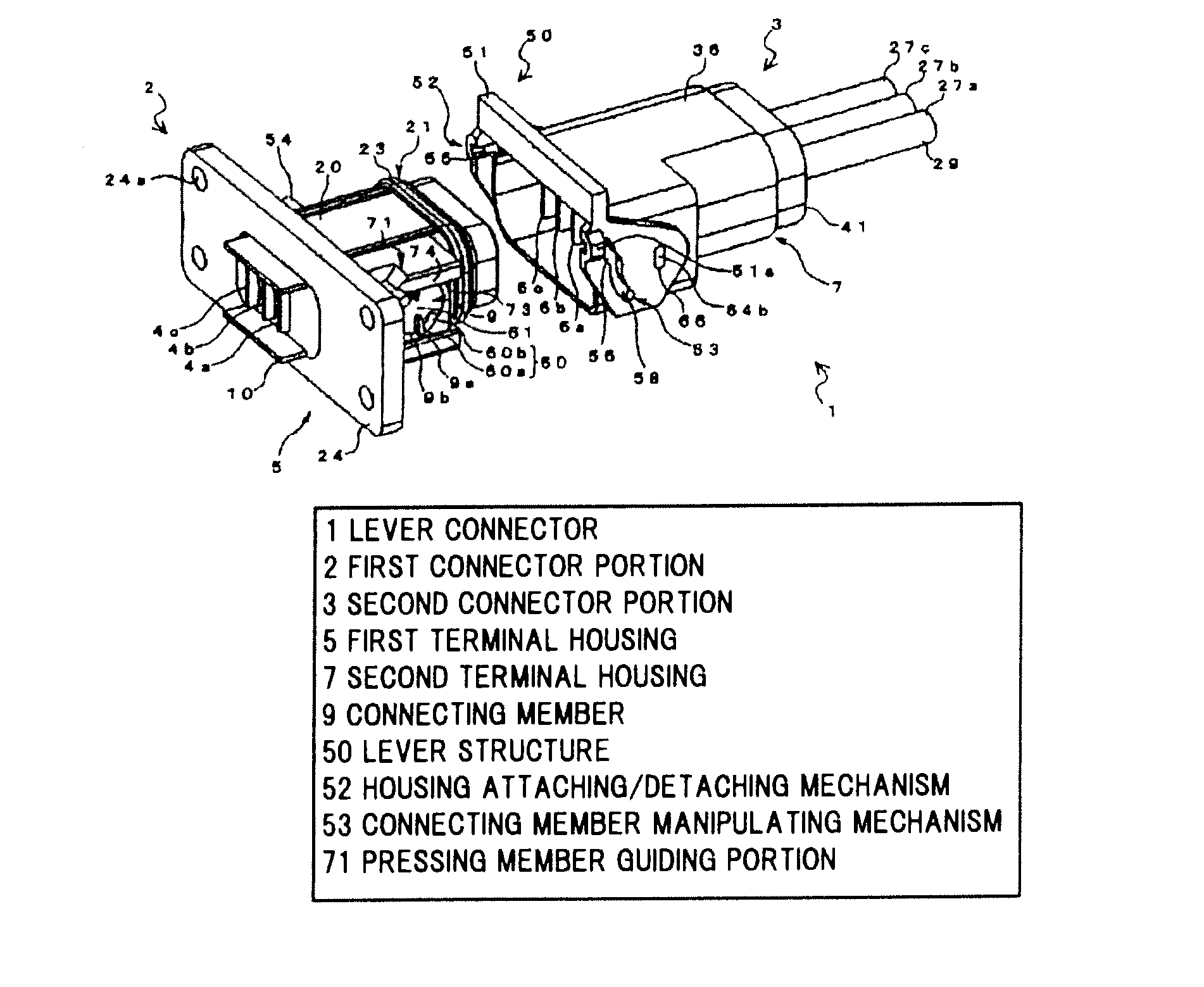
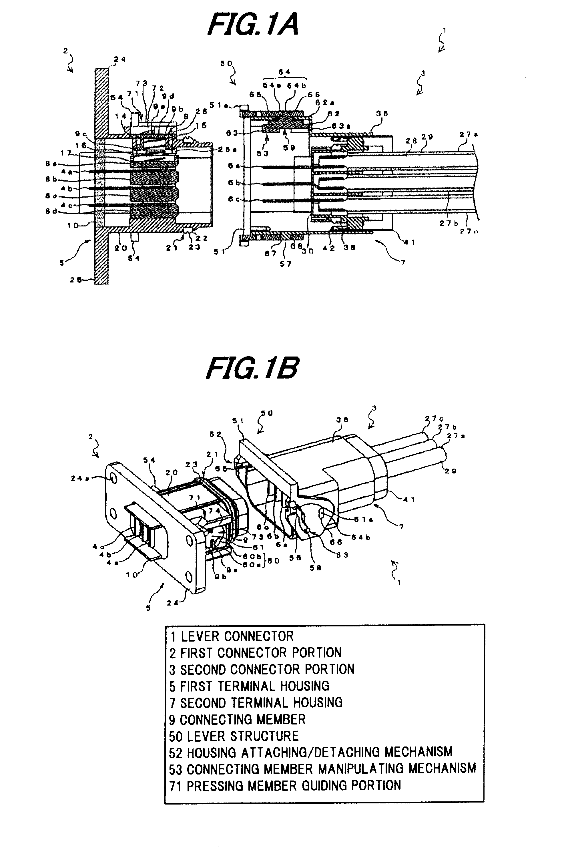
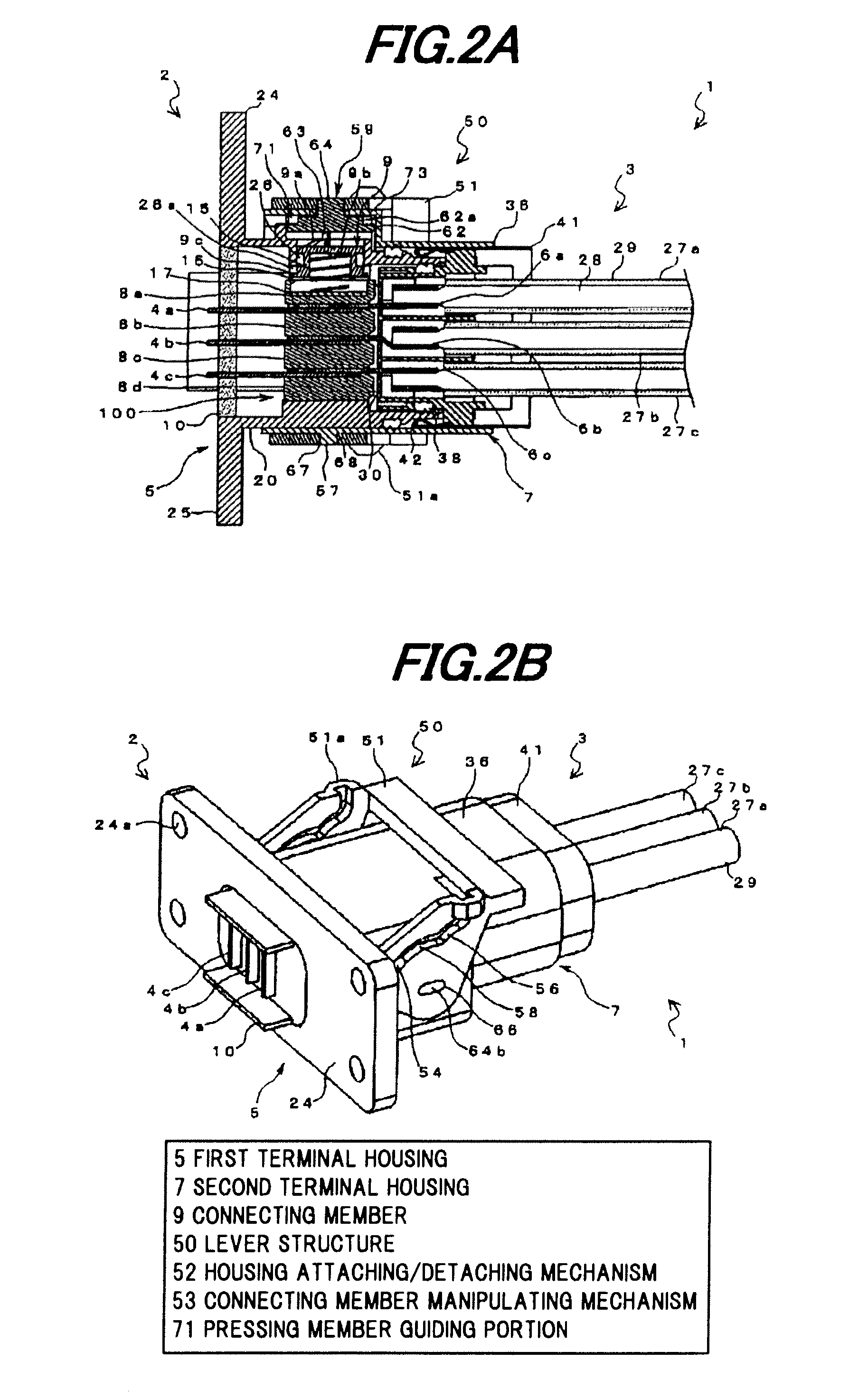
[0065]FIGS. 1A and 1B are a cross-sectional view and a perspective view, respectively, showing a lever connector before mating two connector portions, in one embodiment according to the invention, and FIGS. 2A and 2B are a cross-sectional view and a perspective view, respectively, showing the lever connector of FIGS. 1A and 1B when mating the two connector portions, and setting a turn lever into a fixing position.

[0066]Lever Connector 1 Structure

[0067]As shown in FIGS. 1A to 2B, the lever connector 1 in this embodiment is constructed of a first connector portion 2 and a second connector portion 3, which are mated with each other, to thereby collectively connect a plurality of power lines.

[0068]More specifically, the lever connector 1 includes the first connector portion 2 having a first terminal housing (male terminal housing) 5 with a plurality of (three) first connect...


PUM


Abstract

A lever connector includes a first connector portion including a first terminal housing with a plurality of first connecting terminals, a second connector portion including a second terminal housing with a plurality of second connecting terminals, a plurality of isolating plates, a connecting member to fix the first and second connecting terminals at the contacts therebetween, and a lever structure including a turn lever provided to hold both sides of either one of the first or second terminal housing. The lever structure includes a connecting member manipulating mechanism for turning the turn lever to manipulate the connecting member to apply a pressing force to each of the contacts or release the applying of that pressing force. The connecting member manipulating mechanism includes a contact holding means for maintaining the electrical connections between the first and second connecting terminals, respectively, even in the event of the absence of the turn lever.

Description

[0001]The present application is based on Japanese patent application No. 2010-092515 filed on Apr. 13, 2010, the entire contents of which are incorporated herein by reference.BACKGROUND OF THE INVENTION[0002]1. Field of the Invention[0003]The present invention relates to a lever connector, for use in eco-friendly cars, such as hybrid vehicles, electric vehicles and the like, and in particular, for being capable of use for a power harness, which is used for large power transmission.[0004]2. Description of the Related Art[0005]In hybrid vehicles, electric vehicles and the like which have remarkably developed in recent years, a power harness, which is used for large power transmission for connection between devices, has at its one end a connector, which consists of two separate portions: a male connector portion with a male terminal and a first terminal housing accommodating that male terminal, and a female connector portion with a female terminal connected with the male terminal and ...

Claims


Application Information

Patent Timeline
Patent Type & Authority Applications(United States)
IPC IPC(8): H01R13/62
CPCH01R13/62933H01R13/521
Inventor SUZUKI, SACHIOTAKEHARA, HIDEAKIFUKUDA, KUNIHIROKATAOKA, YUTAUMETSU, JUNHAYASHI, SHINYA
Owner HITACHI METALS LTD
Why Eureka
Try Eureka