Travelling wave thermoacoustic piezoelectric system for generating electrical energy from heat energy

a piezoelectric system and travel wave technology, applied in the direction of generator/motor, machine/engine, lighting and heating apparatus, etc., can solve the problem of still required movement of the thermoacoustic engine mass

Inactive Publication Date: 2011-10-20
KING ABDULAZIZ CITY FOR SCIENCE AND TECHNOLOGY
View PDF10 Cites 15 Cited by
  • Summary
  • Abstract
  • Description
  • Claims
  • Application Information

AI Technical Summary

Problems solved by technology

However, the use of the moving masses in the thermoacou...

Method used


Image

  • Travelling wave thermoacoustic piezoelectric system for generating electrical energy from heat energy
  • Travelling wave thermoacoustic piezoelectric system for generating electrical energy from heat energy
  • Travelling wave thermoacoustic piezoelectric system for generating electrical energy from heat energy

Examples


Embodiment Construction

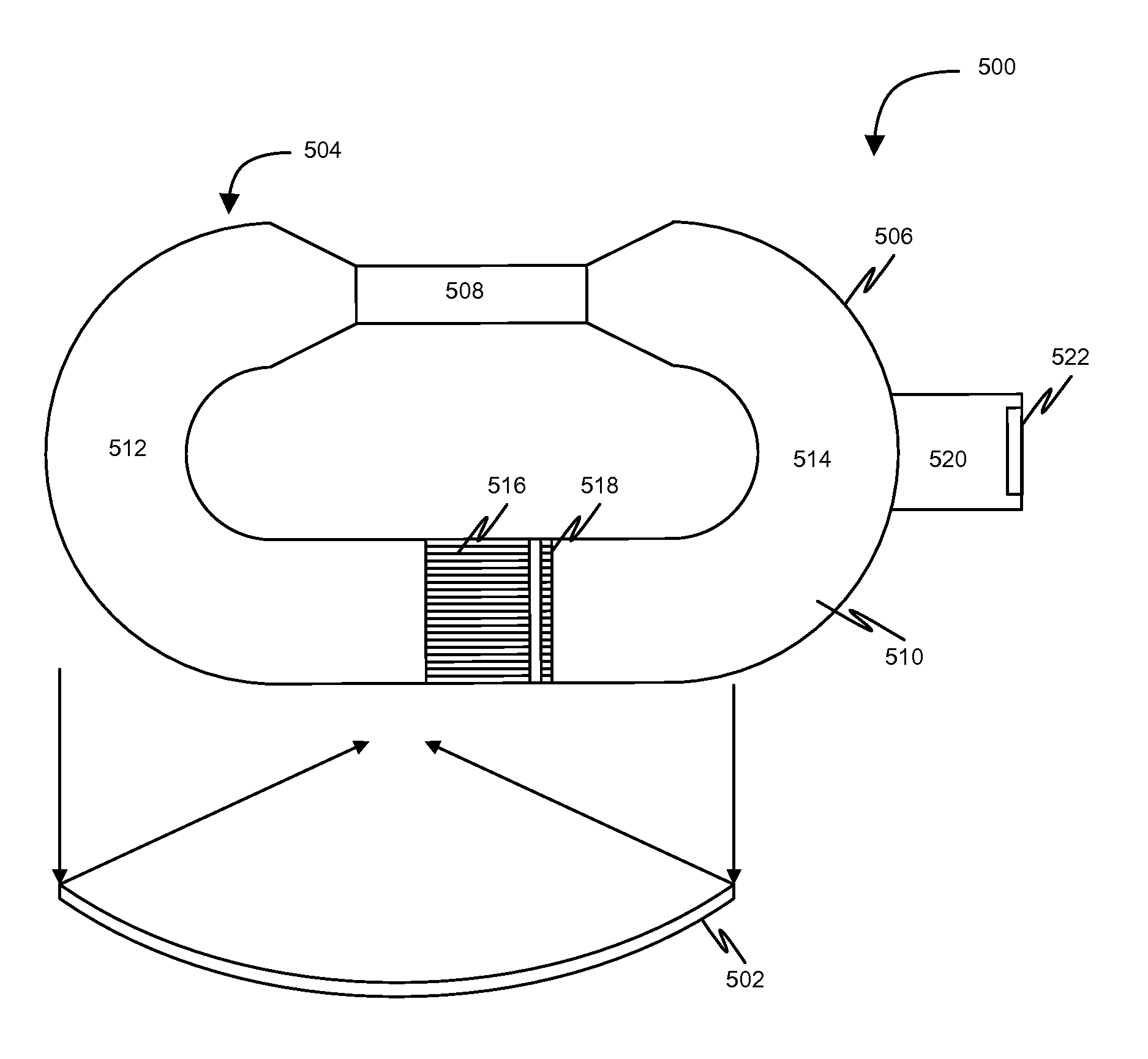
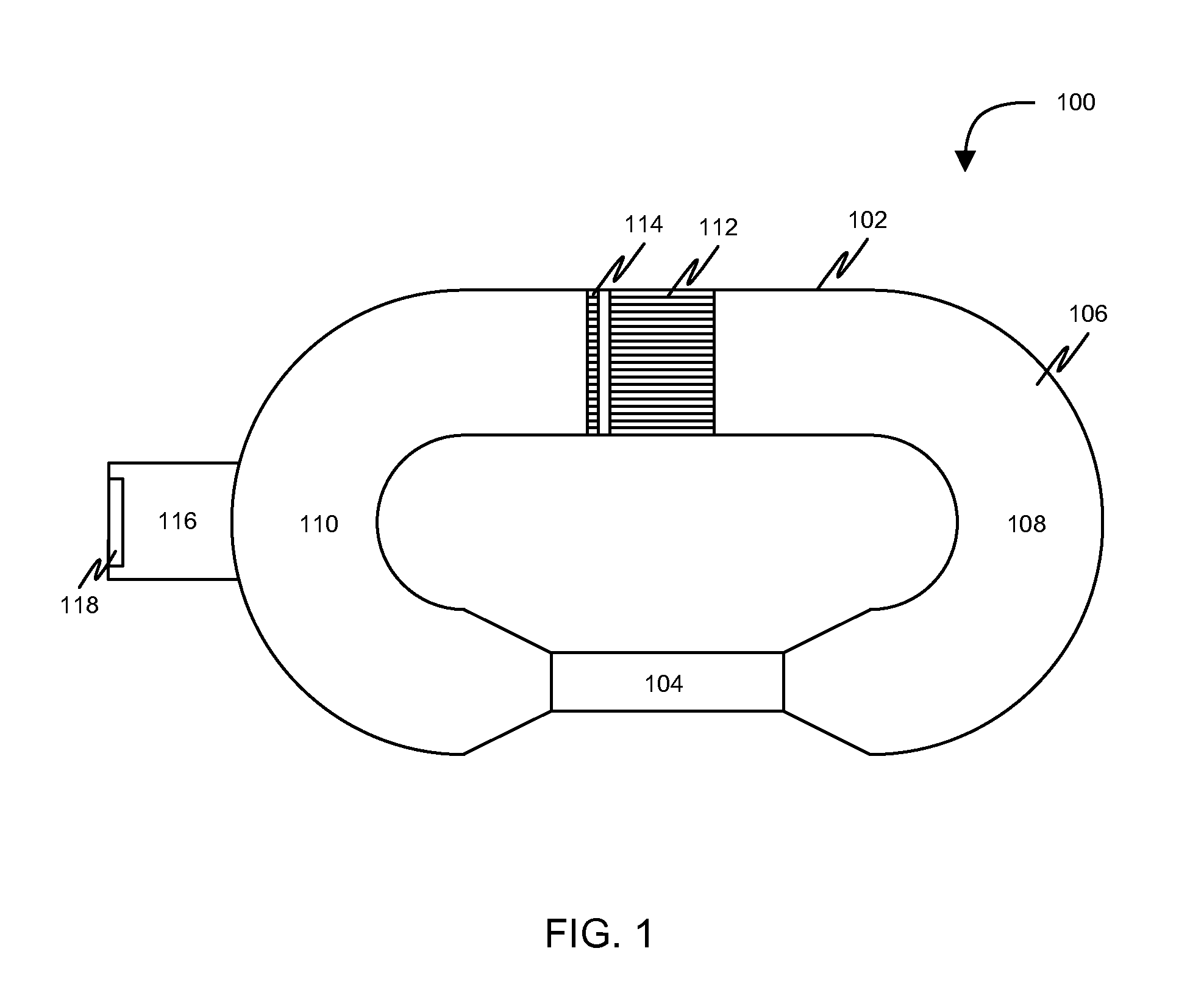
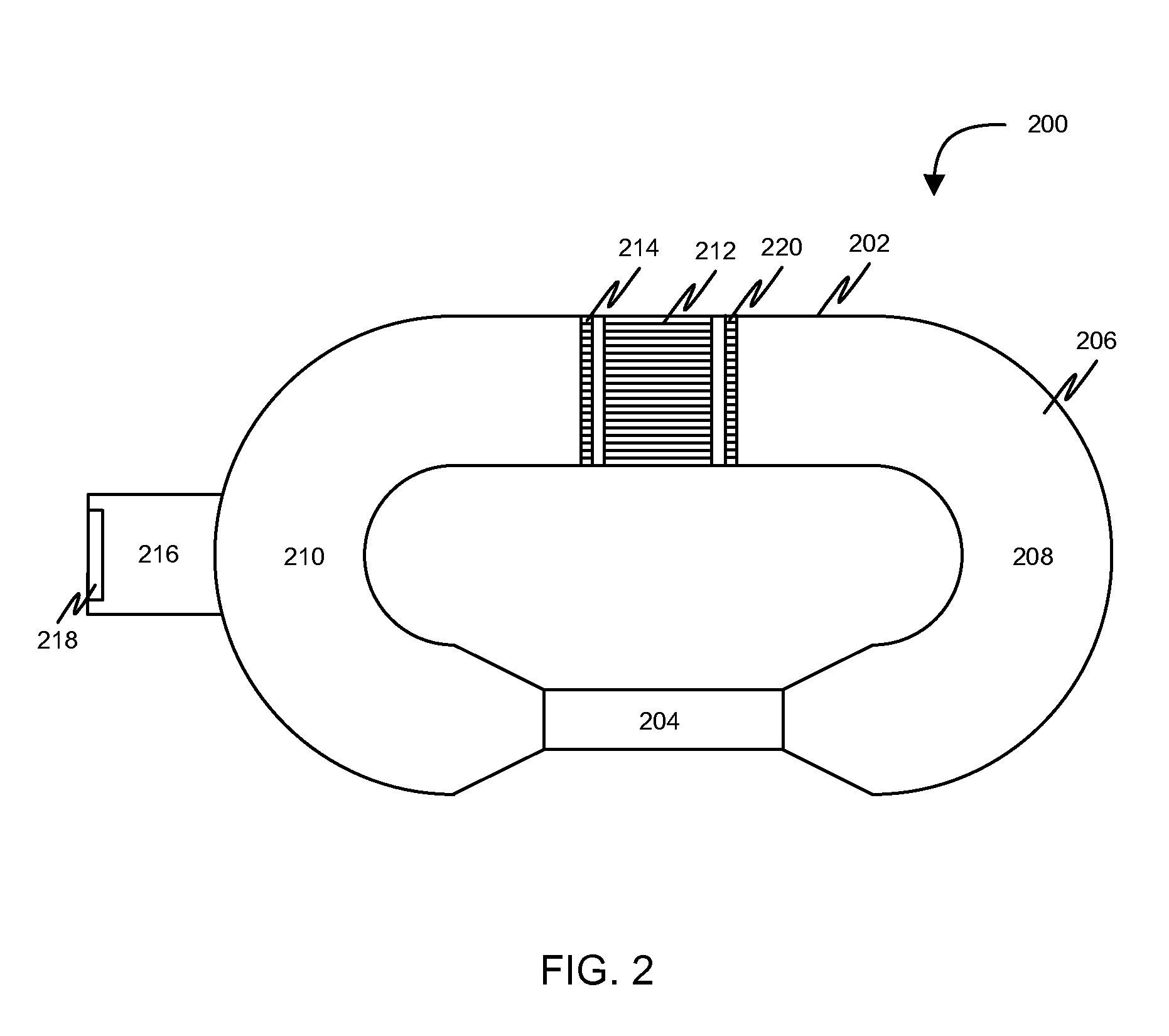
[0014]Before describing in detail embodiments that are in accordance with the invention, it should be observed that the embodiments reside primarily in combinations of method steps and apparatus components related to a travelling wave thermoacoustic piezoelectric apparatus and system components related to a travelling wave thermoacoustic piezoelectric system. Accordingly, the apparatus components, method steps and system components have been represented where appropriate by conventional symbols in the drawings, showing only those specific details that are pertinent to understanding the embodiments of the invention so as not to obscure the disclosure with details that will be readily apparent to those of ordinary skill in the art having the benefit of the description herein.

[0015]In this document, relational terms such as first and second, top and bottom, and the like may be used solely to distinguish one entity or action from another entity or action without necessarily requiring or...


PUM


Abstract

A travelling wave thermoacoustic piezoelectric apparatus capable of generating electrical energy from heat energy is provided. The travelling wave thermoacoustic piezoelectric apparatus includes a hosing with two ends connected by an inertance component, a porous stack, a resonator, and a piezoelectric bimorph. The housing comprises a compressible fluid and has a first portion and a second portion. The first portion receives heat energy from a heat source for creating a temperature gradient between the first portion and the second portion. A cold heat exchanger within the second portion is positioned at one end of the porous stack. The compressible fluid traverses between the first portion and the second portion through the porous stack and the inertance component to generate travelling acoustic waves. The travelling acoustic waves resonate with the resonator for generating acoustic energy. The piezoelectric bimorph positioned at an end of the resonator opposite to an end of the resonator connected to the second portion, oscillates based on the acoustic energy for generating the electrical energy.

Description

FIELD OF THE INVENTION[0001]The invention generally relates to generating electrical energy from heat energy, and more specifically, to a travelling wave thermoacoustic piezoelectric system for generating electrical energy from heat energy using travelling thermoacoustic waves.BACKGROUND OF THE INVENTION[0002]Nowadays thermoacoustic engines are commonly used as heat pumps or refrigerators. The thermoacoustic engines utilize energy associated with thermoacoustic waves to generate electrical energy.[0003]In existing technologies, usually thermoacoustic engines receive heat from a heat source and use a large part of the heat to generate thermoacoustic waves. Further, energy associated with the thermoacoustic waves may be used to perform various types of works. In order to use the energy associated with the thermoacoustic waves, the thermoacoustic engines use a hot heat exchanger and a cold heat exchanger. A porous structure may be configured between the hot heat exchanger and the cold ...

Claims


Application Information

Patent Timeline
IPC IPC(8): F25B21/00F25B27/00
CPCF02G1/043F02G2243/54H02N2/18F02G2280/10F02G2254/30
Inventor ALDRAIHEM, OSAMA J.
Owner KING ABDULAZIZ CITY FOR SCIENCE AND TECHNOLOGY
Why Eureka
Try Eureka