
Ntc/ptc heating pad

a heating pad and ptc technology, applied in ohmic resistance heating, separation processes, chemistry apparatuses and processes, etc., can solve the problems of limited control, insufficient sensitivity to provide desired temperature control accuracy, and limited temperature control precision, so as to achieve positive control of the temperature of the heating pad and the effect of positive control of heat generation

Inactive Publication Date: 2011-10-27
HELEN OF TROY LIMITED
View PDF2 Cites 10 Cited by
  • Summary
  • Abstract
  • Description
  • Claims
  • Application Information

AI Technical Summary

Benefits of technology

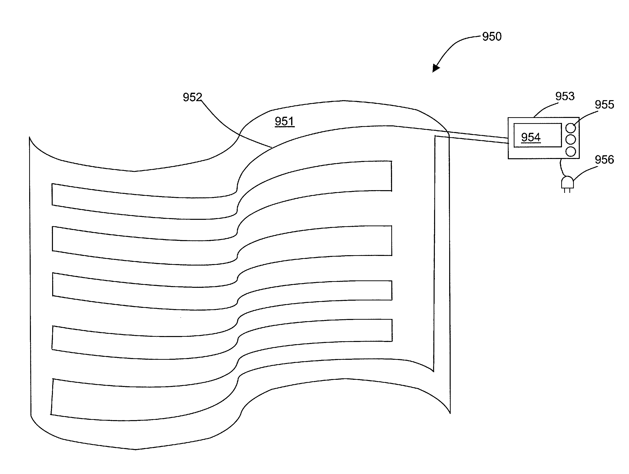
[0008]Embodiments of the invention disclosed herein use feedback from an NTC signal, or from both PTC and NTC signals, in order to provide positive control of the temperature of the heating pad. These embodiments of the invention provide alternative methods to control heating pad temperature, under a variety of conditions such as covered, uncovered, folded over, etc The more precise, positive control of heat generation at or near an over-heated condition of the heating pad allows for incorporation of additional safety controls, and can allow for the shut down of power to the heating pad before the heating pad becomes over heated.
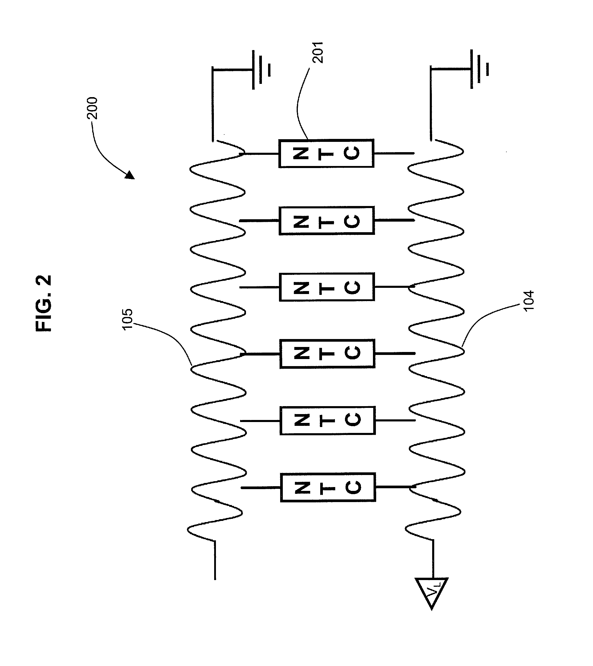
[0014]Advantages of embodiments of the invention further include use of a simple control method, thereby allowing for a low-cost design. The control method may achieve a similar or slightly faster warm-up time than is generally known in the art. The control method can be implemented using conventional, lower-cost wiring, thereby providing for a low-cost design. The control method may also detect fault conditions in the heating pad more quickly than the conventional art, by the detection of an anomalous pattern of NTC resistance, or an anomalous combination of NTC and PTC resistances, thereby permitting the heating pad to be shut down before the fault conditions can cause overheating.

Problems solved by technology

Limited control can be accomplished by detection of a low-resistance path at a hot spot between heating and sensing wires.
A drawback of the conventional approaches is that the precision of the temperature control is limited by the sensitivity of the temperature-sensing material or the method of processing feedback provided from the temperature-sensing material.
Over at least a portion of the temperature range of interest, the sensitivity may not be adequate to provide a desired accuracy of temperature control.
Furthermore, known control algorithms may be susceptible to degraded accuracy under a variety of conditions, such as the heating pad being partially covered, uncovered, folded over, etc.

Method used


Image

  • Ntc/ptc heating pad
  • Ntc/ptc heating pad
  • Ntc/ptc heating pad

Examples


first embodiment

[0040]Referring now to FIG. 4, there is shown a simplified electrical diagram of a sensing circuit 300 to sense the resistance of the combination of NTC and PTC materials, and convert the resistance into electrical signals for use as feedback to a controller. Power source 305 supplies power through switch 304 to conductor 311. The resistance of the conductor 311 is represented by lumped resistors 301a, 301b (Rpm and RPTC2), but it should be understood that the resistance is distributed throughout the length of conductor 311. A first (PTC) sensing resistor 308 is connected in series with conductor 311, and the first sensing resistor 308 is connected to electrical ground. A sensing point 309 is used to measure the voltage across first sensing resistor 308.

[0041]An electrical path through resistive material 102 to return electrical conductor 312 is represented by a single lumped resistor 303, but it should be understood that the resistance of the resistive material 102 is distributed a...

second embodiment

[0047]Referring now to FIG. 5, there is shown a simplified electrical diagram of a sensing circuit 400 to sense the resistance of the combination of NTC and PTC materials, and convert the resistance into electrical signals for use as feedback to a controller. When switch 404 is in a closed position, power source 405 supplies power through switch 404 to electrical conductor 411. First (PTC) sensing resistor 408 electrically connects from conductor 411 to electrical ground. When switch 404 is in open position, current flows through resistor 421, conductor 412, resistive material 102 and resistor 422, conductor 411 and resistor 408 to ground. NTC detect sensing point 410 is used only when switch 404 is switched to an open position. The voltages at sensing point 409 when switch 404 is closed is determined in accordance with equation (5):

VPTC=VL*R3 / (R3+RPTC1+RPTC2)  (5)

[0048]When switch 404 is in an open position, power source 405 no longer supplies power directly to electrical conductor...


PUM

PropertyMeasurementUnit
Temperatureaaaaaaaaaa
Flexibilityaaaaaaaaaa
Currentaaaaaaaaaa

Abstract

A controllable heating pad, having a heating conductor embedded in the heating pad, a sensing conductor embedded in the heating pad, a resistive material providing a distributed electrical path between the heating conductor and the sensing conductor, a first current sensor to sense a current in the heating conductor and a second current sensor to sense a current in the sensing conductor. A method of controlling a temperature of a heating pad, including the steps of: warming the heating pad to at least a first predetermined temperature by use of an adjustable on / off signal to the controllable switch, measuring currents through an NTC material or a combination of a PTC material and an NTC material; and maintaining a temperature of the heating pad to within a predetermined temperature range by use of the adjustable on / off signal to the controllable switch.

Description

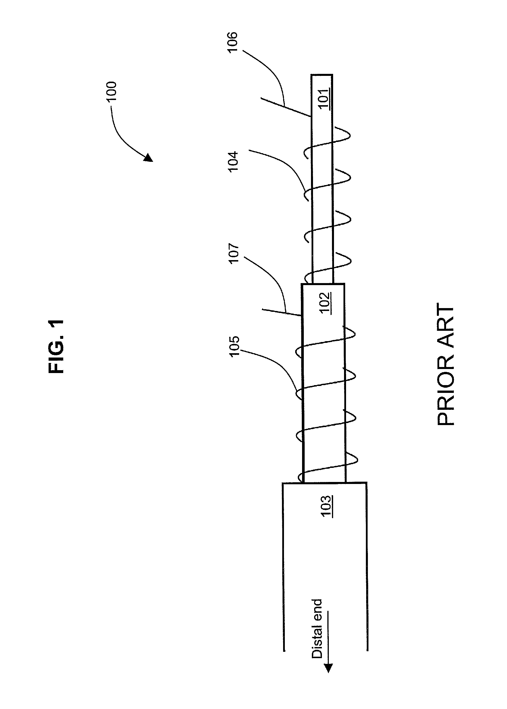
BACKGROUND OF THE INVENTION[0001]Heating pads and electric blankets are devices used to keep an object warmer than a surrounding temperature. For instance, they may be used to keep a person warm in a bed, or to warm a limb (e.g., an electric mitten), an animal (e.g., an electric pet blanket), an object (e.g., a pipe heater to thaw a pipe or prevent a pipe from freezing), etc. Heating pads and electric blankets in general will be referred herein as “heating pads,” unless the circumstances clearly indicate otherwise. Additional layers of insulation may be used with a heating pad, such as an outer layer of insulation to lessen heat loss, or an inner partially-insulative layer to lessen a risk from a hot spot in the heating pad excessively heating an adjacent portion of the object. The additional layers of insulation may be included with the heating pad, or may be external to the heating pad (e.g., an ordinary bed blanket, comforter, or the like), spread over at least a portion of the h...

Claims


Application Information

Patent Timeline
IPC IPC(8): H05B1/02H05B3/34
CPCH05B1/0252H05B3/34H05B2203/009H05B2203/003H05B3/56
Inventor WANG, ZHIJINGZHONG, RUMAODUAN, HECHUANG
Owner HELEN OF TROY LIMITED
Learn More