System for use in illumination of railway feature

a technology for railway features and lighting systems, applied in the field of railways, can solve problems such as injuries and injuries of maintenance personnel

Inactive Publication Date: 2011-10-27
TRIPSPLUSONE
View PDF4 Cites 17 Cited by
  • Summary
  • Abstract
  • Description
  • Claims
  • Application Information

AI Technical Summary

Problems solved by technology

In the maintenance of railways, injuries have been observed.
For example, maintenance personnel have been

Method used


Image

  • System for use in illumination of railway feature
  • System for use in illumination of railway feature
  • System for use in illumination of railway feature

Examples


Embodiment Construction

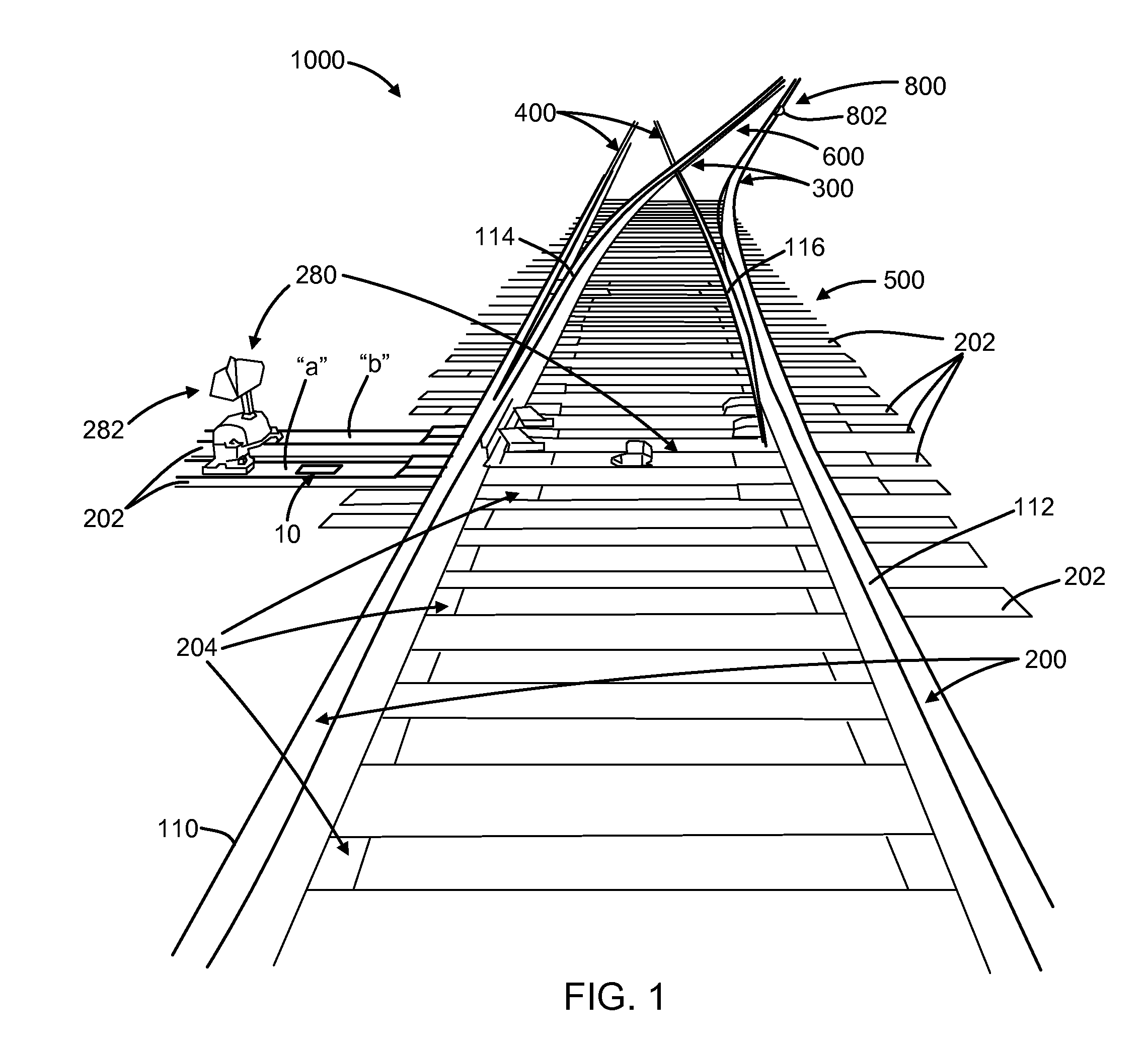
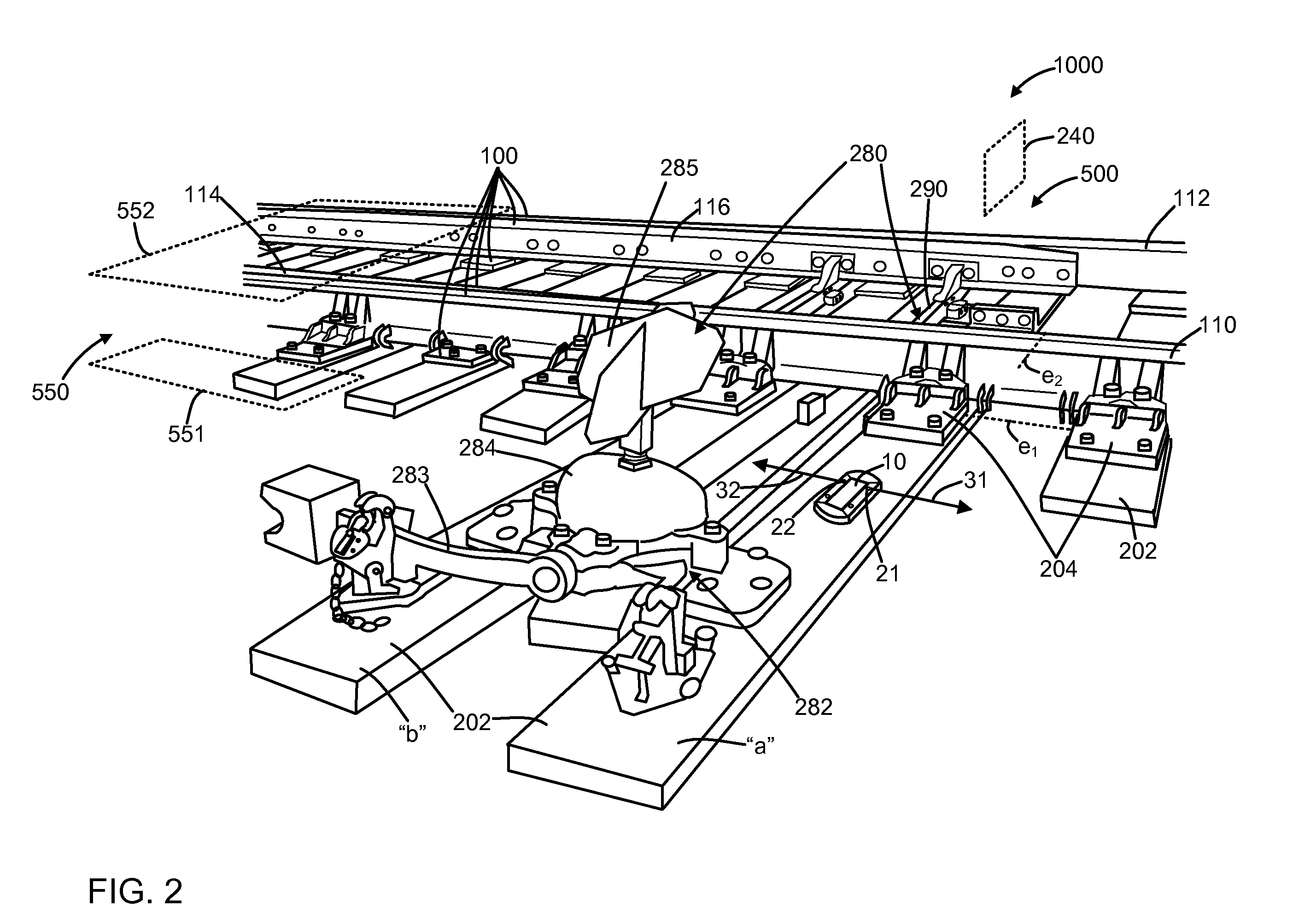
[0018]Referring to FIGS. 1-13, there is set forth herein a system 1000 for illumination of a railway feature. System 1000 can include an illumination unit 10 which can be specifically located and featurized as will be set forth herein. By illumination of a railway feature, a risk of injury posed by a railway feature can be substantially reduced. A railway feature can be e.g., a location of interest, e.g., a switch, or a plurality of locations of interest.

[0019]Referring to illumination unit 10, illumination unit 10 in one embodiment can include a solar panel 30 for collection of solar energy and a light source bank 20. Light source bank 20 can include a plurality of light sources as shown in the embodiment of FIGS. 1-13 or can include a single light source. Illumination unit 10 can include a rechargeable battery 40 as will be set forth herein and can be operative to be recharged utilizing solar energy collected from solar panel 30. Illumination unit 10 can be operative so that durin...


PUM


Abstract

There is provided a system for use in illuminating a feature of a railway. In one embodiment, a system can include an illumination unit disposed for illumination of a railway feature. The illumination unit can include a light source bank, a solar panel, and a rechargeable battery for energizing the light source bank that is rechargeable utilizing energy collected by the solar energy panel.

Description

FIELD OF THE INVENTION[0001]The present invention relates to railways in general and in particular to a system for use in illumination of a feature of a railway.BACKGROUND OF THE PRIOR ART[0002]Railways can comprise a series of interconnected railroad tracks. Railroad tracks typically comprise a system of railroad ties and rails. Railroad ties can be aligned in generally parallel relation to one another and can be spaced to nominal centerline spacing distance of about 53.34 cm (21.00 in.). Railroad tracks can be disposed above a series of ties. A length of railroad track can include a pair of spaced apart rails disposed in perpendicular (transverse) relation to a series of railroad ties. Railroad ties in one embodiment can comprise treated timber, and rails can comprise steel. A railway can include a switch. A switch can include a switchstand (a points lever assembly) and a set of switch rails. Within an area of a switch, railroad ties can be extended substantially outward from a ra...

Claims


Application Information

Patent Timeline
IPC IPC(8): F21L4/04F21L4/02
CPCF21S9/037F21W2111/02B61K13/00B61L2207/02B61L9/04
Inventor MORAN, HENRY A.BRILL, MILTONFORSTER, DANNY THOMAS
Owner TRIPSPLUSONE
Why Eureka
Try Eureka