Double-end threaded body and internally-threaded body

Inactive Publication Date: 2011-10-27
NEJILAW
View PDF12 Cites 31 Cited by
  • Summary
  • Abstract
  • Description
  • Claims
  • Application Information

AI Technical Summary

Benefits of technology

[0056]Thus, by combining the use of the internally-threaded body of the present invention, on which is arranged a plate piece having a spiral thread corresponding to a spiral groove of the opposite orientation of the spiral thread of the internally-threaded body, and the duplex threaded body of the present invention, a locking effect that inhibits loosening structurally instead of inhibiting loosening by frictional force can be obtained even in the case of a so-called single nut type, and a bolt and nut can be obtained that enable their positions to be fixed even at an arbitrary intermediate position on the duplex threaded body.
[0057]In addition, by using a combination of a right-handed internally-threaded body comprised by forming a clockwise spiral thread, a left-handed internally-threaded body comprised by forming a counter-clockwise spiral thread, and the duplex threaded body of the present invention as an externally-threaded body, and coupling the right-handed internally-threaded body and the left-handed internally-threaded body by a suitable method such as welding or coupling means, a locking effect that

Problems solved by technology

Right-handed screws have been nearly exclusively used in conventional screw applications including bolts and nuts used for fastening, while left-handed screws have been limited to special applications such as turnbuckles in which internal threads are formed rotating in different directions along the same axis on both ends thereof.
This type of fastener is composed so that it is difficult for a nut screwed onto a bolt to become loose by making suitable design contrivances to the nut.
In addition, in the case of conventional single-nut type anti-loosening nuts, although a certain degree of locking effects can be obtained with a single nut, since urging force is simply generated with a washer-like plate piece to tighten meshing of the bolt and nut in a single spiral groove on t

Method used


Image

  • Double-end threaded body and internally-threaded body
  • Double-end threaded body and internally-threaded body
  • Double-end threaded body and internally-threaded body

Examples


Embodiment Construction

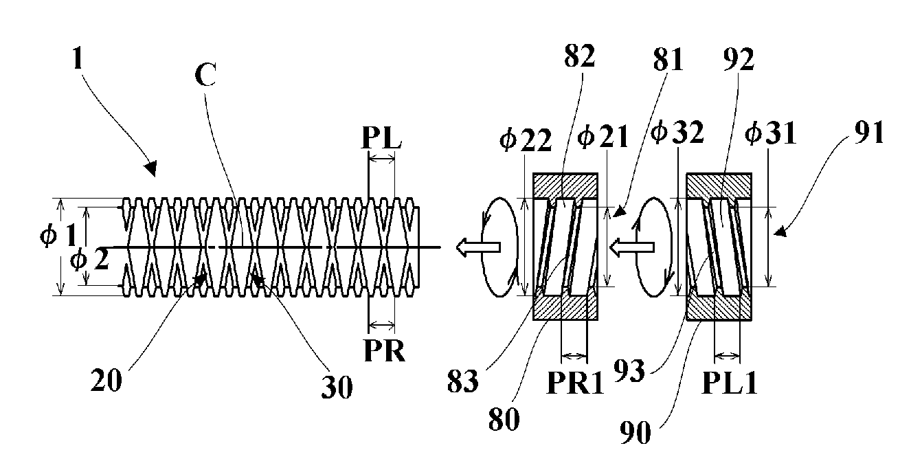
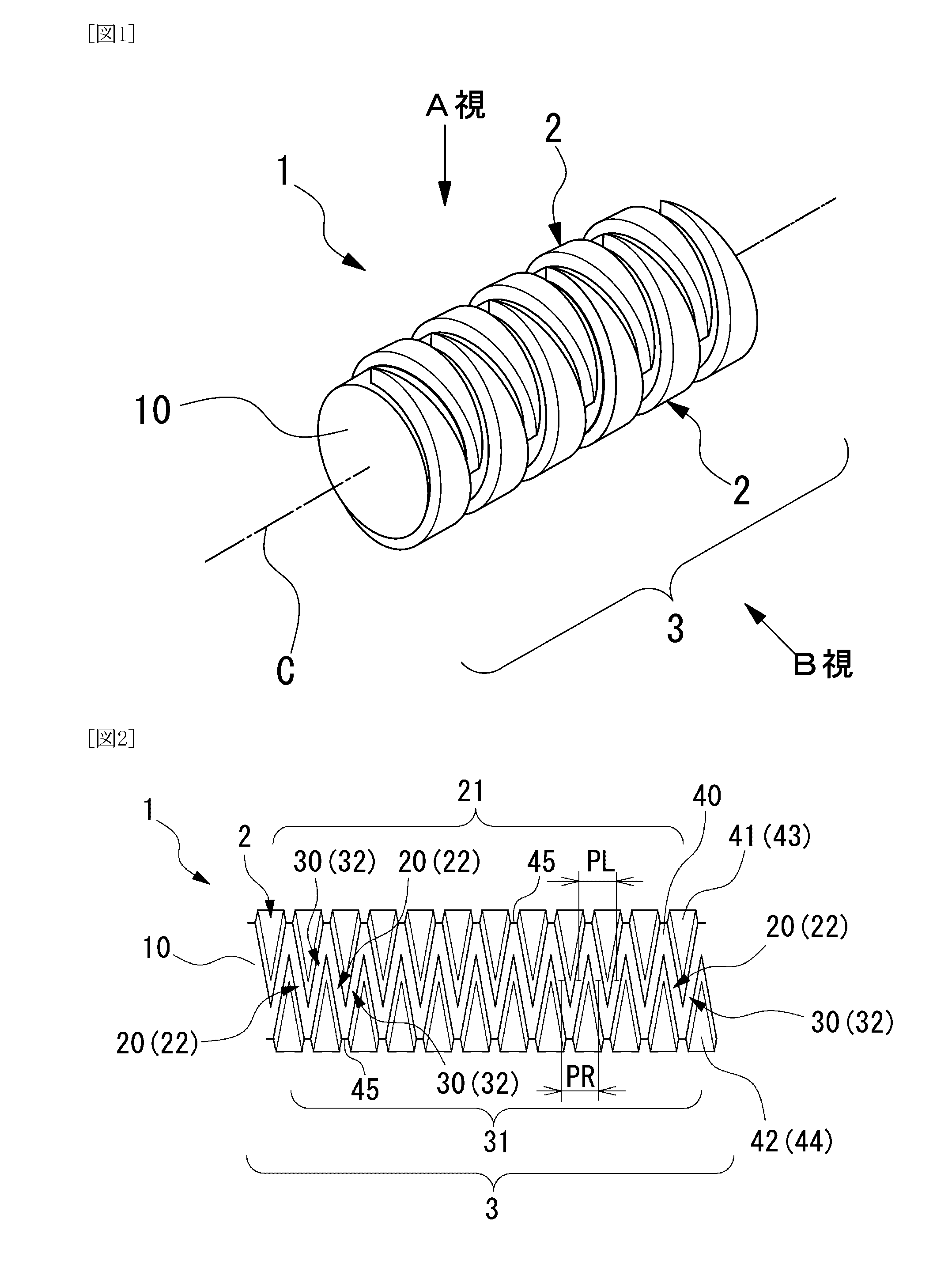
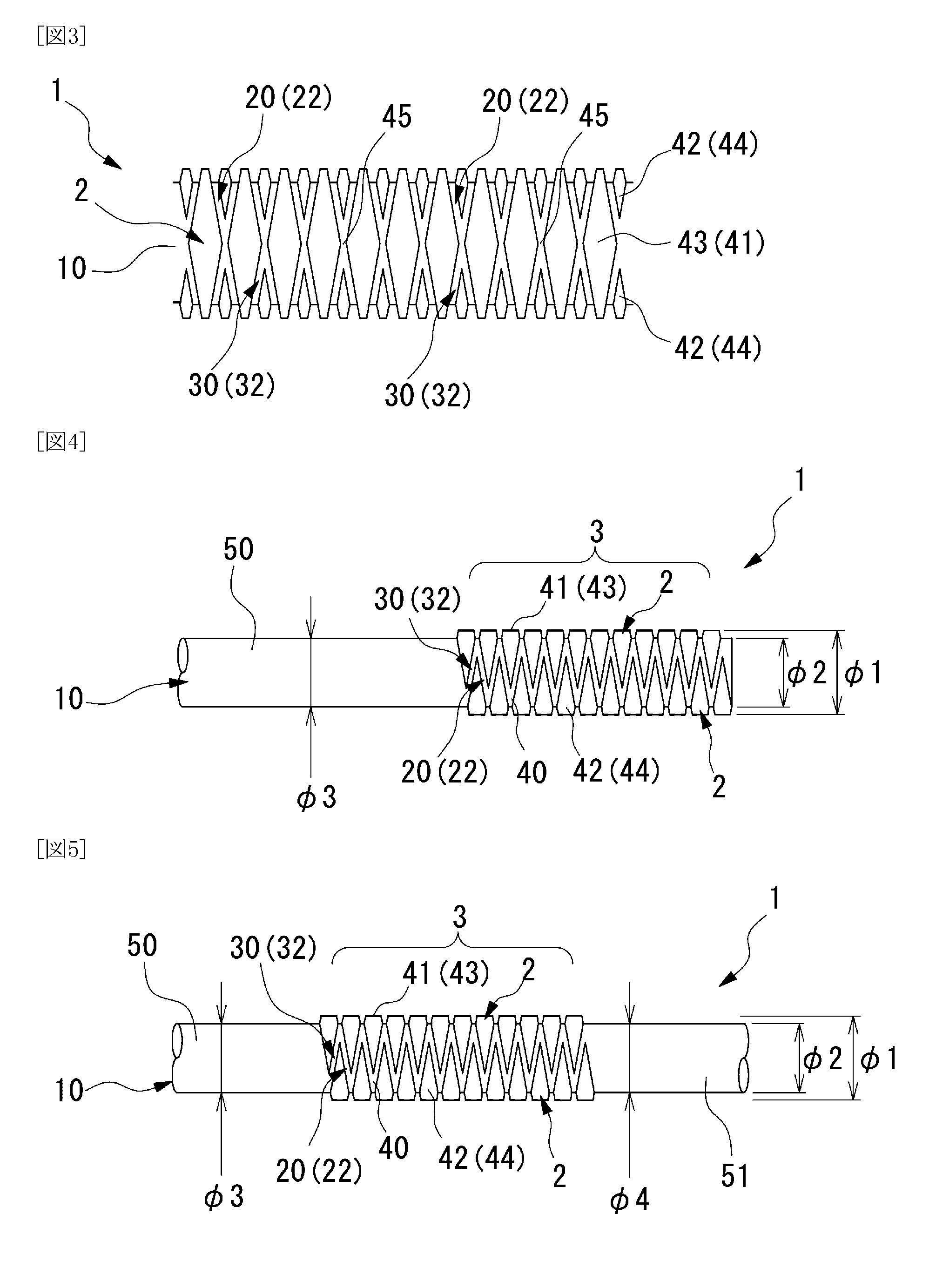
[0416]In a first aspect thereof, a first preferred embodiment of the duplex threaded body of the present invention is explained in detail with reference to the attached drawings (FIGS. 1 to 6) using the example of a duplex threaded body 1 comprised by forming a right-handed thread 20 and a left-handed thread 30 overlapping in the same region on the outer circumferential surface of a rod-like member 10.

[0417]Furthermore, a non-circular end portion (not shown) in the shape of a non-circular hole or non-circular column or non-circular tube may be formed on one end or both ends of the duplex threaded body 1. This non-circular end portion can be formed into the shape of a hexagonal column or hexagonal tube having a hexagonal transverse cross section having an inscribed circle of a diameter equal to or greater than the diameter of the rod-like member 10, or can be in the form of a hexagonal hole and the like provided in the shape of a hexagon on one end of the rod-like member 10 at a pres...


PUM


Abstract

An object of the present invention is to provide a duplex threaded body having a right-handed thread and a left-handed thread on the circumferential surface of a single solid member. In addition, an object of the present invention is to provide a single-nut or double-nut type internally-threaded body that demonstrates a locking effect even at an intermediate position without substantially loosening by using a combination of a duplex externally-threaded body and one or more internally-threaded bodies. Moreover, an object of the present invention is to provide a screw structure in which a pair of internally-threaded bodies can only be removed by destruction once they are mutually coupled when screwed onto a duplex externally-threaded body, thereby making it possible to impart tamper-proof characteristics in addition to a locking effect. The duplex externally-threaded body of the present invention has, on the outer circumferential surface of a rod-like member, an overlapping region in which a clockwise spiral right-handed thread and a counter-clockwise spiral left-handed thread are provided in at least an overlapping manner. Moreover, the present invention makes it possible to use, alone or in combination, a right-handed internally-threaded body in which a right-handed thread is formed, and a left-handed internally-threaded body in which a left-handed thread is formed, that are screwed onto a duplex externally-threaded body.

Description

TECHNICAL FIELD[0001]The present invention relates to a threaded body having spiral threads formed in the outer circumferential surface or inner circumferential surface of a fixing member, and more particularly, to a duplex threaded body having a right-handed thread and a left-handed thread in which the spiral threads are composed of a clockwise spiral thread and a counter-clockwise spiral thread.BACKGROUND ART[0002]So-called screws, which are comprised by forming a thread along spiral path, namely a helix, depicted on the outer circumferential surface of rod by moving the center of a circular path along the central axis of the rod, have proliferated extensively as fundamental components used in industry. When broadly categorized according to the direction in which their threads are wound, screws are classified into right-handed screws, in which the thread extends clockwise in the positive axial direction, and left-handed screws, in which the thread extends counter-clockwise in the ...

Claims


Application Information

Patent Timeline
IPC IPC(8): F16B39/02F16B37/00
CPCF16B33/006F16B33/02F16B35/00F16B37/00F16B39/12F16B39/26F16B39/30F16B39/32F16B39/38F16B2033/025F16H1/16F16H25/24F16B39/282F16B35/04
Inventor MICHIWAKI, HIROSHI
Owner NEJILAW
Why Eureka
Try Eureka