Method and apparatus for measuring a fluid parameter in a vibrating meter

a technology fluid parameter, which is applied in the direction of liquid/fluent solid measurement, instruments, specific gravity measurement, etc., can solve the problems of vibrating flow meter errors, high cost, and inability to accurately measure fluid parameters,

Active Publication Date: 2011-10-27
MICRO MOTION INC
View PDF6 Cites 23 Cited by
  • Summary
  • Abstract
  • Description
  • Claims
  • Application Information

AI Technical Summary

Problems solved by technology

One potential source for error in vibrating flow meters is caused by compressibility, also known as velocity of sound effects.
These errors generally increase with increasing tube oscillation frequency and therefore, the errors often occur during high frequency operation.
This approach is not only more costly, but may be impractical in many situations due to space and cost restrictions.

Method used


Image

  • Method and apparatus for measuring a fluid parameter in a vibrating meter
  • Method and apparatus for measuring a fluid parameter in a vibrating meter
  • Method and apparatus for measuring a fluid parameter in a vibrating meter

Examples


Embodiment Construction

[0117]FIGS. 1-8 and the following description depict specific examples to teach those skilled in the art how to make and use the best mode of the invention. For the purpose of teaching inventive principles, some conventional aspects have been simplified or omitted. Those skilled in the art will appreciate variations from these examples that fall within the scope of the invention. Those skilled in the art will appreciate that the features described below can be combined in various ways to form multiple variations of the invention. As a result, the invention is not limited to the specific examples described below, but only by the claims and their equivalents.

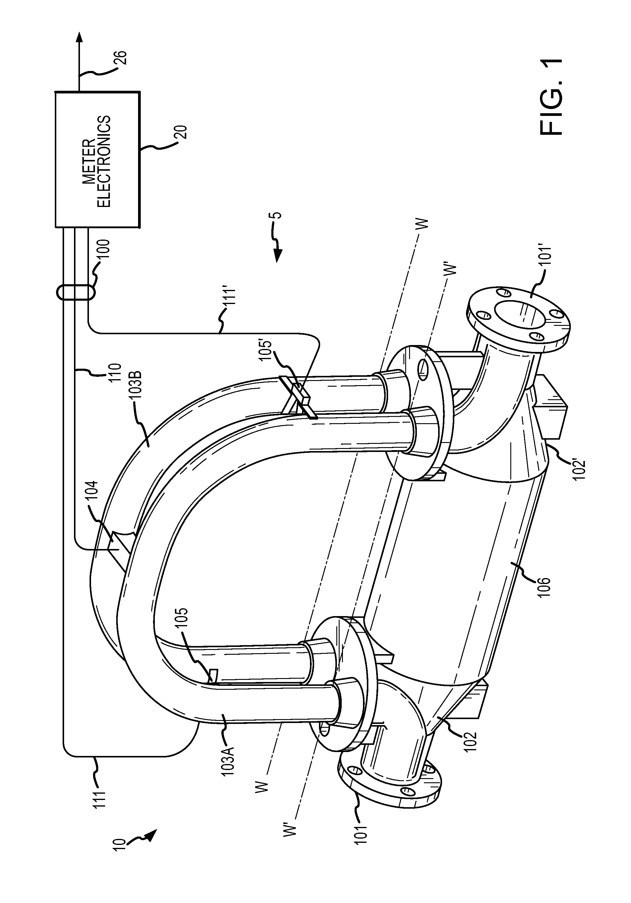
[0118]FIG. 1 shows a vibrating meter 5 comprising a flow meter assembly 10 and meter electronics 20. The meter electronics 20 is connected to the meter assembly 10 via leads 100 and is configured to provide measurements of one or more of a density, mass flow rate, volume flow rate, totalized mass flow, temperature, velocity of sou...


PUM

PropertyMeasurementUnit
frequenciesaaaaaaaaaa
fluid propertyaaaaaaaaaa
densityaaaaaaaaaa

Abstract

A method for calculating a fluid parameter of a fluid flowing through a vibratory flow meter is provided. The method comprises vibrating the flow meter at one or more frequencies and receiving a vibrational response. The method further comprises generating a first fluid property and generating at least a second fluid property. The method further comprises calculating a fluid parameter based on the first fluid property and the at least second fluid property.

Description

TECHNICAL FIELD[0001]The present invention relates to a flow meter, and more particularly, to a method and apparatus for measuring a fluid parameter in a vibrating flow meter.BACKGROUND OF THE INVENTION[0002]Flow meters are used to measure the mass flow rate, density, and other characteristics of flowing materials. The flowing material may comprise a liquid, gas, solids suspended in liquids or gas, or any combination thereof. Vibrating conduit sensors, such as Coriolis mass flow meters and vibrating densitometers typically operate by detecting motion of a vibrating conduit that contains a flowing material. Properties associated with the material in the conduit, such as mass flow, density and the like, can be determined by processing measurement signals received from motion transducers associated with the conduit. The vibration modes of the vibrating material-filled system generally are affected by the combined mass, stiffness, and damping characteristics of the containing conduit an...

Claims


Application Information

Patent Timeline
Patent Type & Authority Applications(United States)
IPC IPC(8): G06F19/00G01F1/05G01N9/00
CPCG01F1/8436G01N9/002G01F1/8477G01F1/84G01N9/00G01N11/16
Inventor WEINSTEIN, JOELBELL, MARK JAMESPATTEN, ANDREW TIMOTHY
Owner MICRO MOTION INC
Why Eureka
Try Eureka