Self-centering vial clamp

a vial clamp and self-centering technology, applied in the field of vial clamps, can solve the problems of increasing the overall processing cost and time, not being needed or economical in non-mass-production situations, and easily damaged glass

Active Publication Date: 2011-11-03
HACH CO
View PDF8 Cites 35 Cited by
  • Summary
  • Abstract
  • Description
  • Claims
  • Application Information

AI Technical Summary

Problems solved by technology

The vials can be formed of any material, but vials are often made from glass due to the relatively inexpensive cost of glass and due to the chemical unreactiveness of glass.
The main drawback is that glass is easily damaged or broken.
Automated handling may work well for processing and handling large and continuing streams of vials, but is typically not needed or economical for non mass-production situations.
Makers of equipment that handle and hold vials desire to minimize the need for a user to manipulate racks, holders, clamps, and so forth, as significant vial handling requirements will increase the overall processing cost and time.
Further, vial handling requirements may detract from the user's ability to devote full attention to the measurements or tests to be performed.
Improper placement and / or alignment of a vial may negatively affect the test, such as where material to be added to a vial is dispensed outside of the vial or is otherwise spilled or wasted Improper placement and / or alignment of a vial may damage the vial, such as where a probe is to be inserted into the vial as part of a process.
Where the vial is glass or a similar breakable material, any misalignment may cause damage to or breakage of the vial Improper placement and / or alignment of a vial can damage the associated instrument Improper placement and / or alignment of a vial can cause the vial to be tipped, resulting in spillage of expensive materials.

Method used


Image

  • Self-centering vial clamp
  • Self-centering vial clamp
  • Self-centering vial clamp

Examples


Embodiment Construction

[0048]FIGS. 1-7 and the following description depict specific examples to teach those skilled in the art how to make and use the best mode of the invention. For the purpose of teaching inventive principles, some conventional aspects have been simplified or omitted. Those skilled in the art will appreciate variations from these examples that fall within the scope of the invention. Those skilled in the art will appreciate that the features described below can be combined in various ways to form multiple variations of the invention. As a result, the invention is not limited to the specific examples described below, but only by the claims and their equivalents.

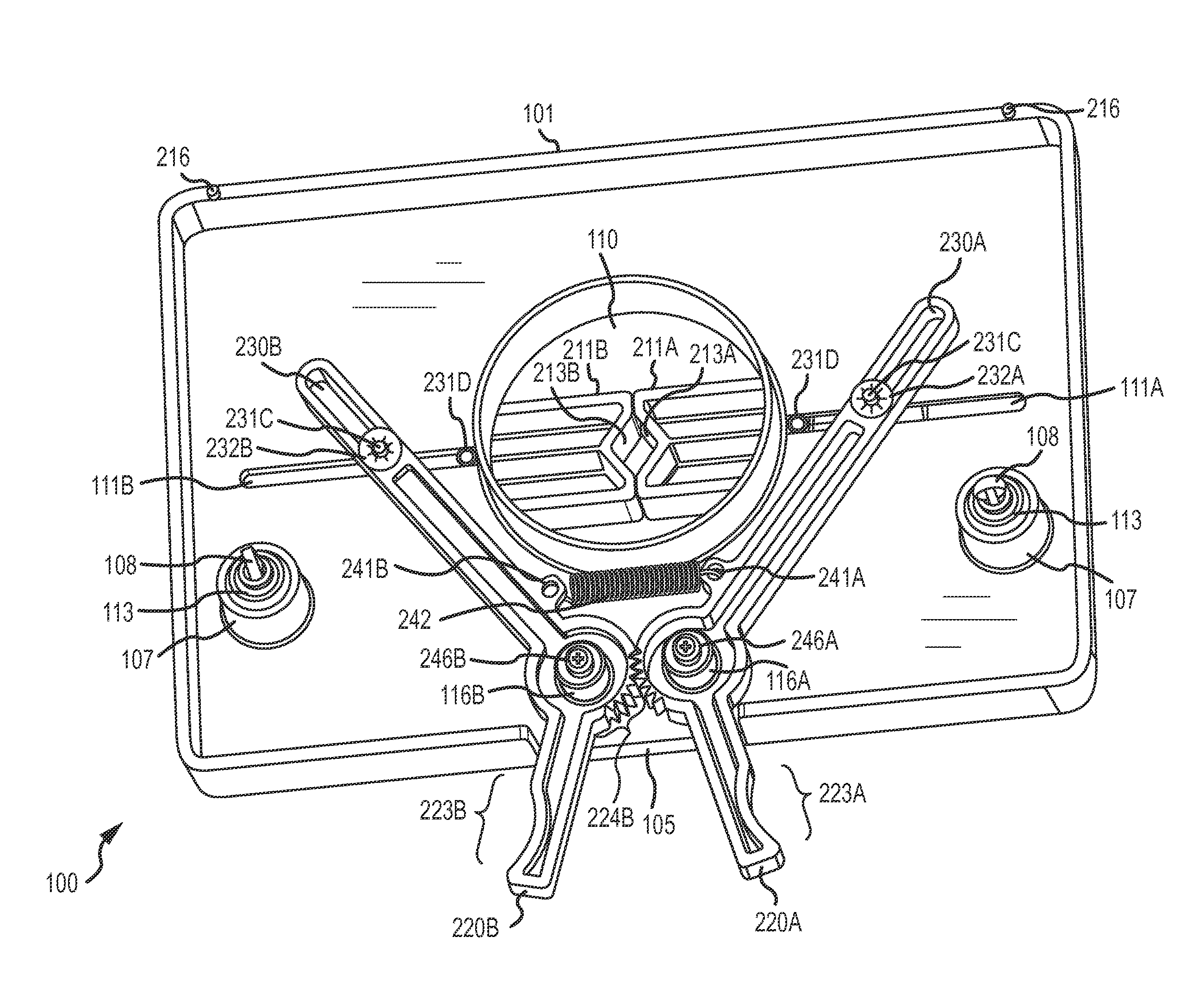
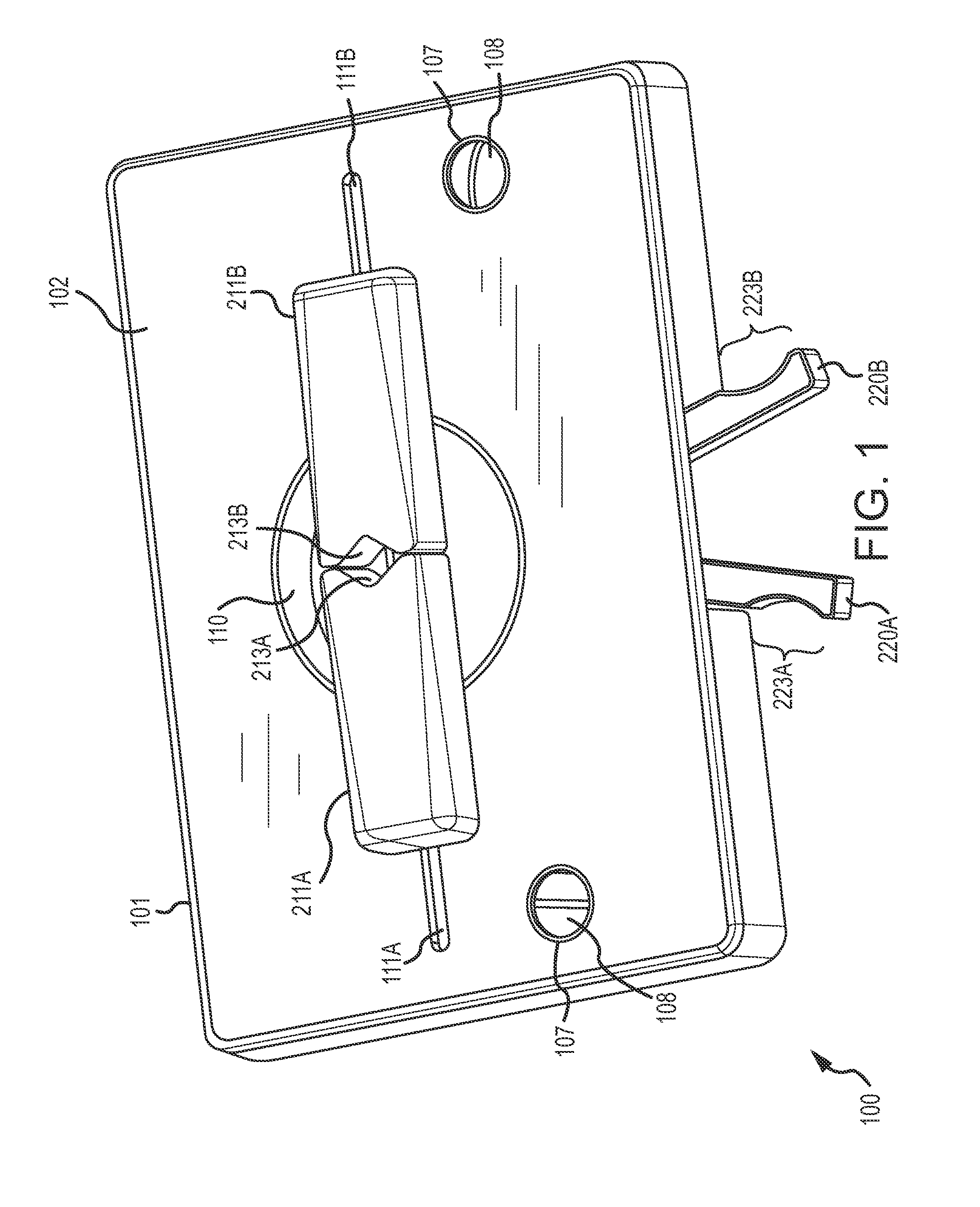
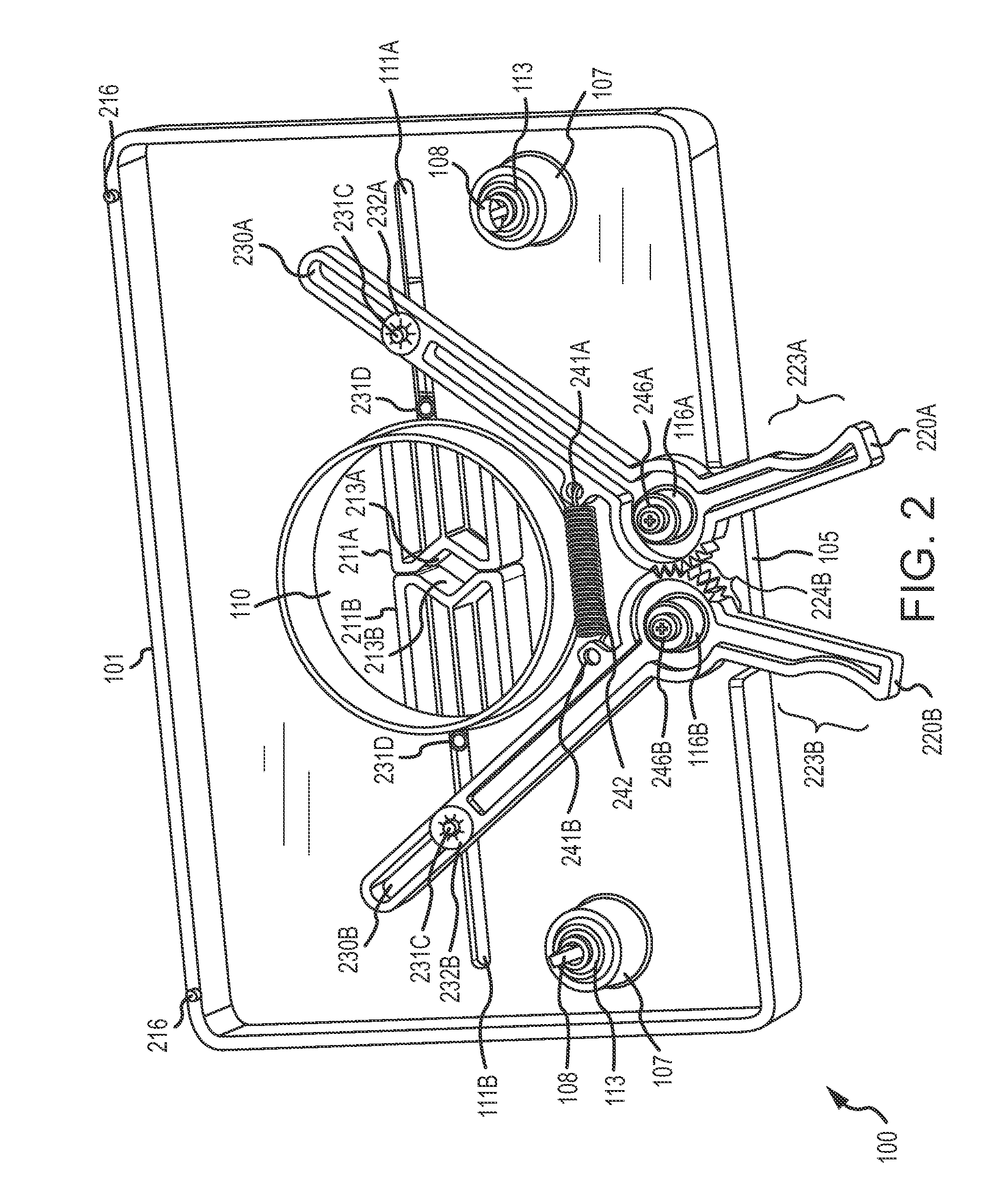
[0049]FIG. 1 shows a self-centering vial clamp 100 according to the invention. The self-centering vial clamp 100 is designed to clamp and hold a vial. The vial can comprise a variety of shapes and sizes. The vial can be formed of any material. The self-centering vial clamp 100 can clamp and hold a vial to be used in various tests ...


PUM

PropertyMeasurementUnit
clamping forceaaaaaaaaaa
sizeaaaaaaaaaa
aperture sizeaaaaaaaaaa

Abstract

A self-centering vial clamp (100) is provided. The self-centering vial clamp (100) includes a clamp body (101) including a vial aperture (110) and two or more jaw slots (111) spaced around the vial aperture (110), two or more clamp jaws (211) spaced around the vial aperture (110), with a clamp jaw (211) including a vial contact face (213) and one or more jaw projections (231) configured to engage a jaw slot (111) of the clamp body (101), and two or more lever arms (220) coupled to the two or more clamp jaws (211). A lever arm (220) is configured to be manually pivoted, wherein the lever arm translates the pivoting motion into a sliding motion of the corresponding clamp jaw (211). Interacting lever gears (224) formed on the lever arms (220) constrain the two or more clamp jaws (211) to move substantially in unison.

Description

[0001]This application claims benefit of, and priority from U.S. provisional patent application No. 61 / 329,174 filed on Apr. 29, 2010 and entitled “Self-Centering Vial Clamp”+BACKGROUND OF THE INVENTION[0002]1. Field of the Invention[0003]The invention is related to the field of a vial clamp, and more particularly, to a self-centering vial clamp.[0004]2. Description of the Prior Art[0005]There are many processes that involve the use and handling of vials of materials. For example, vials may be used to store, transport, and / or test a variety of materials in industrial, scientific, and medical processes, to give a few examples. The vials can be of varying sizes, shapes, and capacities. The vials can be formed of any material, but vials are often made from glass due to the relatively inexpensive cost of glass and due to the chemical unreactiveness of glass. The main drawback is that glass is easily damaged or broken.[0006]In the prior art, vial handling can be automated or manual in na...

Claims


Application Information

Patent Timeline
Patent Type & Authority Applications(United States)
IPC IPC(8): F16B2/10B23P11/00
CPCY10T29/49826A61J1/16B01L2200/023F16B2/12B01L9/50A47J45/10B25B5/02B25B5/04
Inventor WARRICK, BRETBENDER, KEITH
Owner HACH CO
Why Eureka
Try Eureka