Door lock mechanism

Inactive Publication Date: 2011-11-10
SUZUKI MOTOR CORP
View PDF1 Cites 6 Cited by
  • Summary
  • Abstract
  • Description
  • Claims
  • Application Information

AI Technical Summary

Benefits of technology

[0019]According to the structure described above, it is possible to provide a simple door lock mechanism which prevents a door opening and locking at the time of a side impact.

Problems solved by technology

Otherwise, because the upper end of said key rod is fixed to the key cylinder, if the key rod moves excessively in a horizontal direction, the key rod bends and the part below the point where the bend occurs is pulled in an upwards direction to result in locking.

Method used


Image

  • Door lock mechanism
  • Door lock mechanism
  • Door lock mechanism

Examples


first embodiment

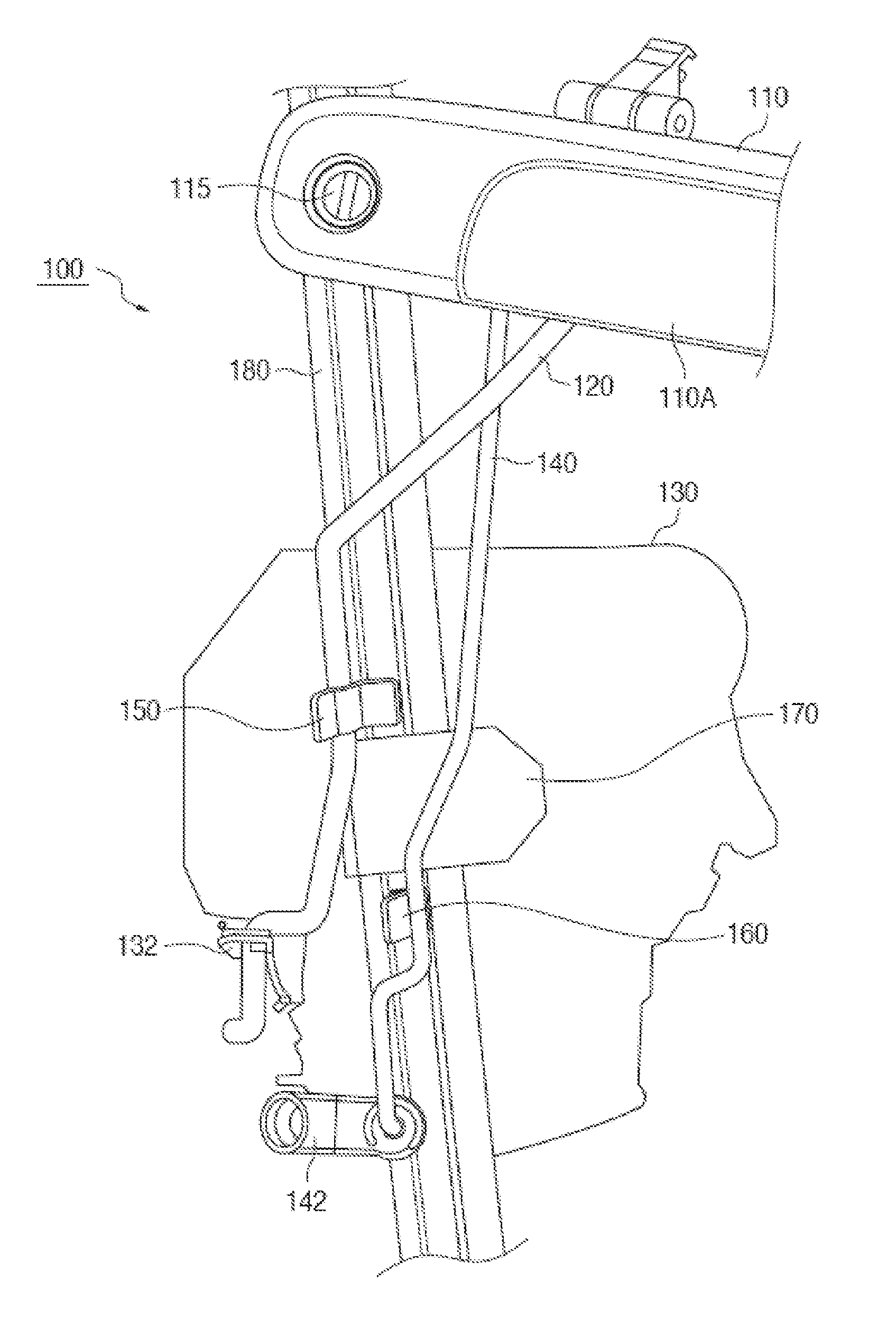
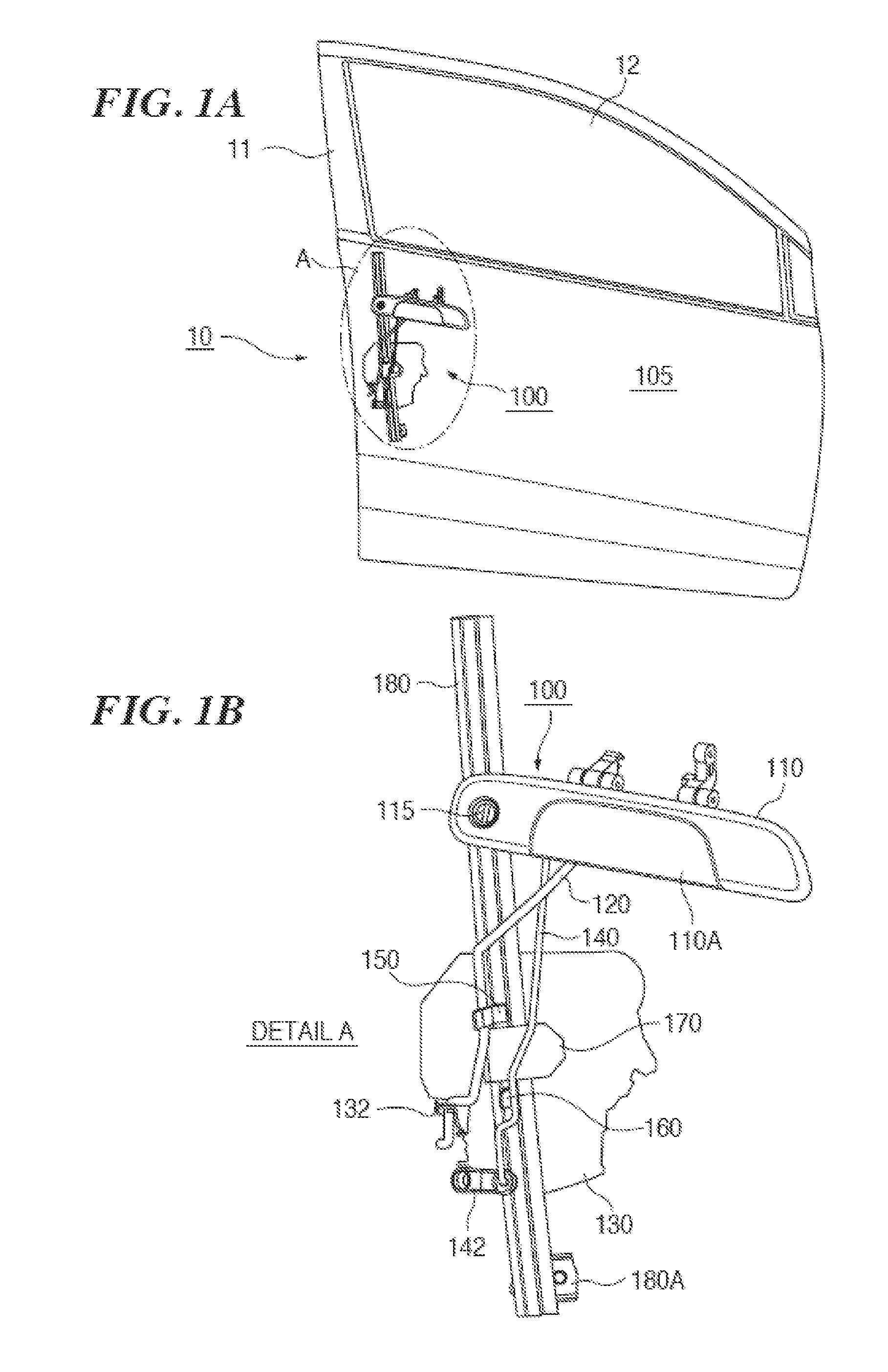
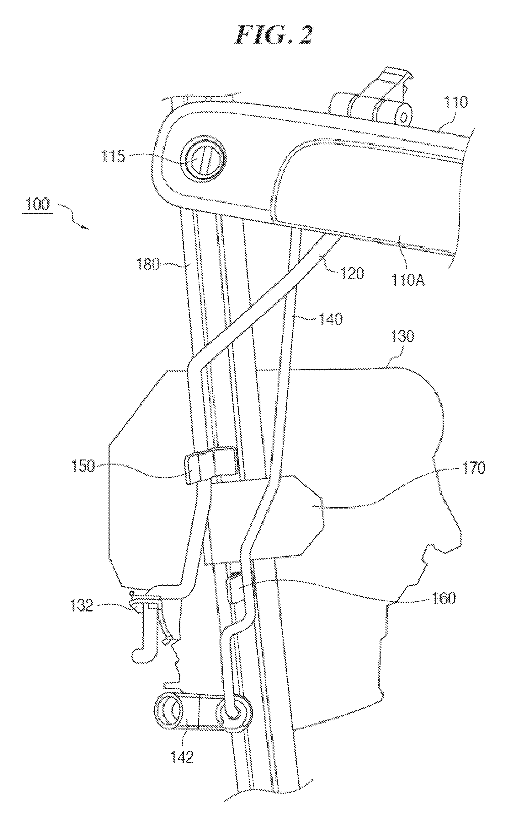
[0029]FIGS. 1A and 1B are diagrams which show a first embodiment of a door lock mechanism according to the present invention. FIG. 1A is a perspective view of a door outer panel 105 on the right side of the vehicle seen from the outside of the vehicle. The door lock mechanism 100 is provided with a door handle 110 which includes a turning grip part 110A. A key cylinder 115 is incorporated into the door handle 110. However, the key cylinder 115 may be arranged separately from the door handle 110 and may be attached to the door outer panel 105. Actually, when observed from the vehicle outside as is shown in FIG. 1A, components other than the door handle 110 do not appear to be hidden by the door outer panel 105.

[0030]The door lock mechanism 100 is provided with a rod shaped open rod 120, which opens the door 10 by engaging with the grip part 110A and moving in a first direction (downwards in the present embodiment). That is, the open rod 120 is arranged in a roughly up / down direction ...

second embodiment

[0056]FIGS. 7A and 7B are diagrams which show a second embodiment of a door lock mechanism according to the present invention. In the present embodiment, only the points which are different to the first embodiment with respect to the door lock mechanism 200 will be explained below. The open rod 220 in the present embodiment includes a first crank part 220A and the key rod 240 includes a second crank 240A.

[0057]FIGS. 7A and 7B show the state before the door outer panel 105 received a side surface collision and the state after the door outer panel 105 receives a side surface collision. In the present embodiment, the displacement restricting part 170 is positioned between first crank part 220A and second crank 240A and more to the inside of the vehicle than the first crank part 220A and second crank 240A and is fixed to the vehicle chassis (door sash 180). When the open rod 22 and the key rod 240 receive a side surface collision, they are pushed by the deformed door outer panel 105 and...


PUM


Abstract

A door lock mechanism 100 comprises a door handle 110 including a turning grip part 110A, an open rod 120 which engages with the turning of the grip part 110A and opens a door by moving in a first direction, a key rod 140 which is linked to a key cylinder 115 and locks the door by moving in a second direction, a first engaging part 150 which is attached to open rod 120 and protrudes in a direction which intersects a movement direction of open rod 120, a second engaging part 160 which is attached to key rod 140 and protrudes in a direction which intersects a movement direction of key rod 140, and a displacement restricting part 170 which is fixed to the vehicle body and positioned further to the inside of the vehicle than first engaging part 150 and second engaging part 160.

Description

CROSS-REFERENCE TO RELATED APPLICATIONS[0001]This application is based upon and claims the benefit of priority from the prior Japanese Patent Application No. 2009-257610, filed on Nov. 11, 2009, the entire contents of which are incorporated herein by reference.BACKGROUND OF THE INVENTION[0002]1. Field of the Invention[0003]The present invention relates to a door lock mechanism in which a door is opened by a door handle and locked by a key cylinder.[0004]2. Background of the Invention[0005]When a vehicle receives an impact from the side (called a side surface impact or side impact), opening or locking a door caused by the impact should be avoided.[0006]Patent document 1 (Japanese Laid Open Patent No. S60-55672) discloses, for example, a protrusion part arranged on the inner side of a door outer panel, as a prior art for preventing a door from opening at the time of a side impact. According to this document, when the door outer panel is deformed towards the inside of the vehicle at th...

Claims


Application Information

Patent Timeline
Patent Type & Authority Applications(United States)
IPC IPC(8): E05B65/20E05B83/36B60J5/00E05B77/04E05B79/14
CPCE05B53/00E05B77/12E05B77/04Y10T70/5199Y10T70/5889Y10T292/57
Inventor MURAMATSU, TAKAHIRO
Owner SUZUKI MOTOR CORP
Why Eureka
Try Eureka