Hamilton H.N2 laminar flow diskette wing

a technology of laminar flow and diskette wing, which is applied in the direction of airflow influencers, aircraft stabilisation, heat reducing structures, etc., can solve the problems of not using laminar flow technology, add additional wings, add induced drag, etc., and achieve the effect of increasing induced drag, adding additional lift, and reducing induced drag

Inactive Publication Date: 2011-11-10
HAMILTON TERRY WAYNE
View PDF27 Cites 0 Cited by
  • Summary
  • Abstract
  • Description
  • Claims
  • Application Information

AI Technical Summary

Benefits of technology

[0013]Accordingly, it is a primary object of the present invention to provide a aircraft airfoil such as a wing or a rotor wing for a helicopter or a airfoil blade for a wind generator with a oval diskette that uses laminar air flow to add additional lift without a increase of induced drag, the oval diskette is static in location and can aid the aircraft at any operating flight speed from takeoff, clime, cruse, descent, and landing approach.
[0014]The present invention utilizes an oval diskette shape that is placed above a airfoil at a distance of ½ the oval diskette's width. This is arrived at by knowing the ground effect of aircraft when flown at ½ their wing length above the ground and by knowing of the potential reduction in induced drag due to favorable interference between two wings. A savings of 40% in vortex drag is achieved in aircraft performance when this relationship with flying surfaces is employed. To realize the benefits of the oval diskette placed over a airfoil such as a aircraft wing it is only necessary to insure a 0 to 7 degree positive angle of the oval diskette to the main wings chord.
[0015]This simple addition of an oval diskette with a laminar air flow supported above an aircraft wing will increase aircraft performance in all flight regimes. It will allow an aircraft to fly higher and faster than the aircraft is designed for, and there is also a safety factor that the oval diskette provides in its ability to lift in any direction it meets the airflow. It is symmetrical in cross section with a leading edge for its full circumference. Like a Frisbee it can fly in any direction, this allows it to lift a wing of an aircraft when the aircraft wants to stall and spin.
[0016]By use of one are more oval diskettes along an aircraft airfoil such as a wing or rotor wing, the overall lifting capacity of a aircraft can greatly be improved without changing the performance of a aircraft and requiring no design changes to an aircraft. This would also apply to the blade of an electric wind generator.

Problems solved by technology

The Nowak does not address cruse flight; it is a stall inhibiter design.
Addition of additional wings has long been a problem in the added induced drag that such plane forms bring to a aircraft performance.
And this prior art does not use laminar flow technology, a oval shape lifting surface and a structure for simple attachment to any preexisting wing.
Since D. Davis 1937‘Fluid Foil’ most aviation design has not made much use of the laminar flow technology because of problems of aluminum construction.
The problem with most wing and airfoil designs is found with the flexing of the skin surface of a wing.
Most of these devices must be retracted due to high induced drag and will only serve the aircraft at a specific speed.
The other penalty that is common among the prior art form is one of complexity of mechanical retraction and the weight that is associated with the addition of slats, flaps, vortex generators, and delta flap generators.
Early biplanes had great lift but high drag and thus low maximum speed range.

Method used


Image

  • Hamilton H.N2 laminar flow diskette wing
  • Hamilton H.N2 laminar flow diskette wing
  • Hamilton H.N2 laminar flow diskette wing

Examples


Embodiment Construction

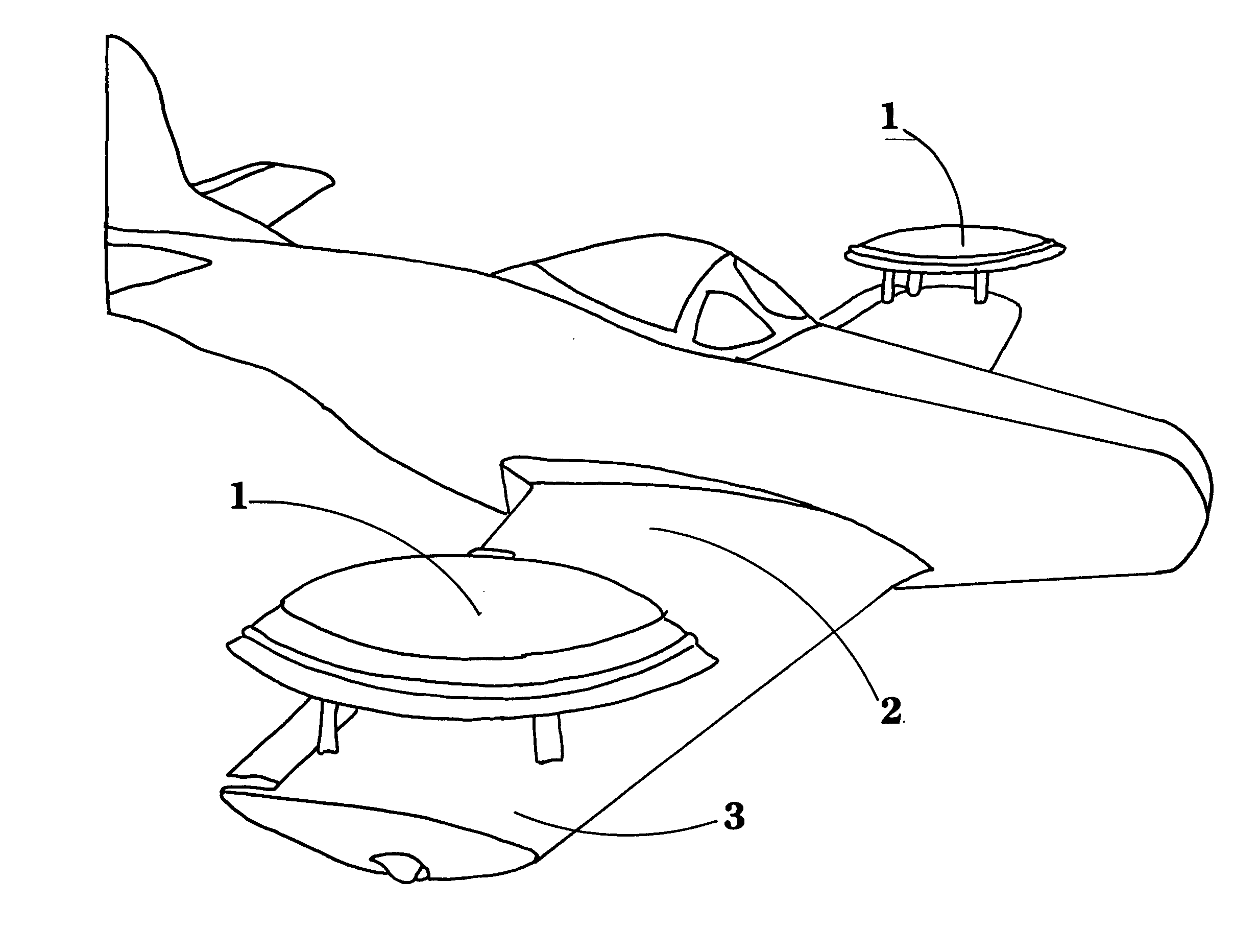
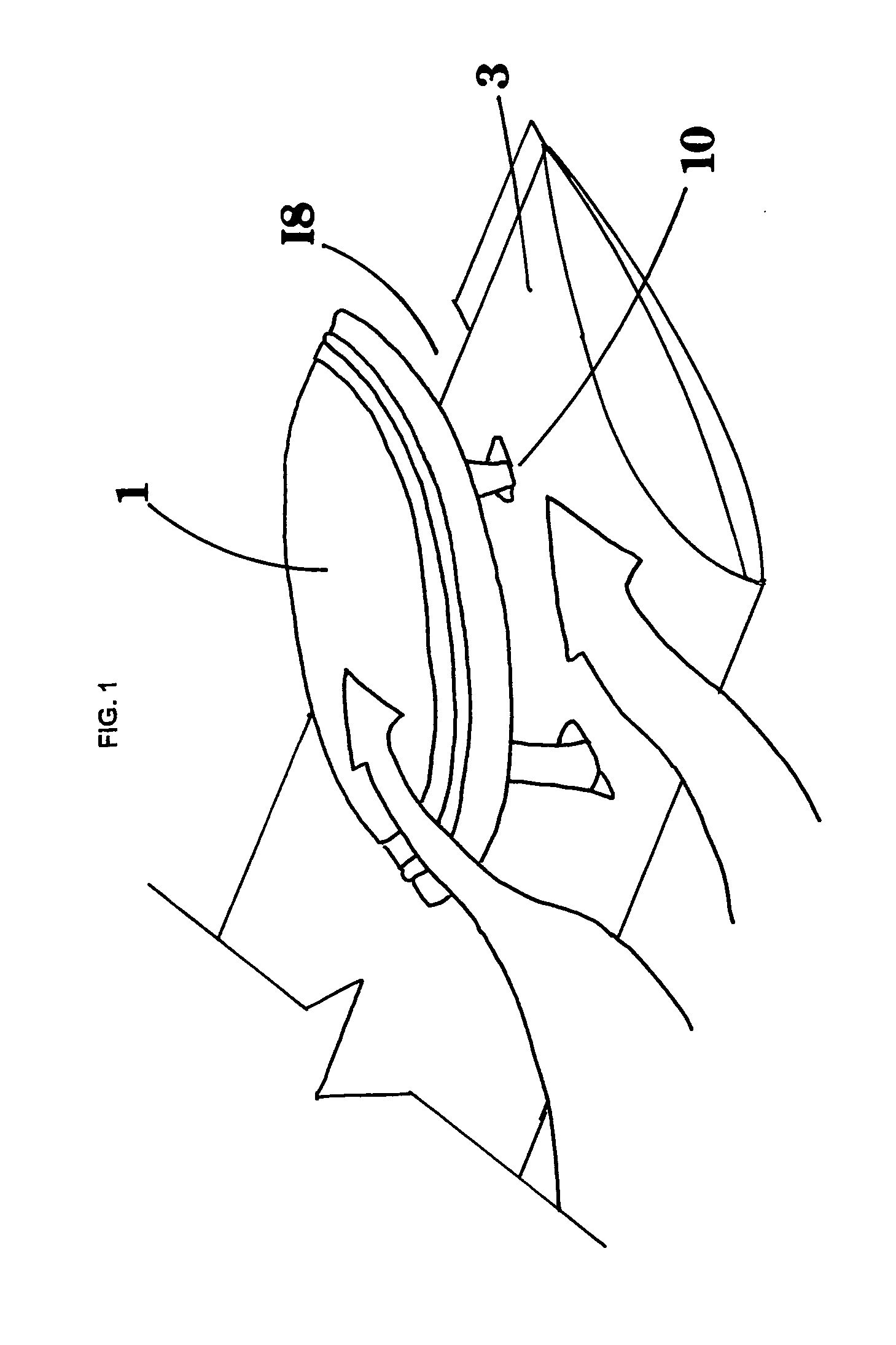
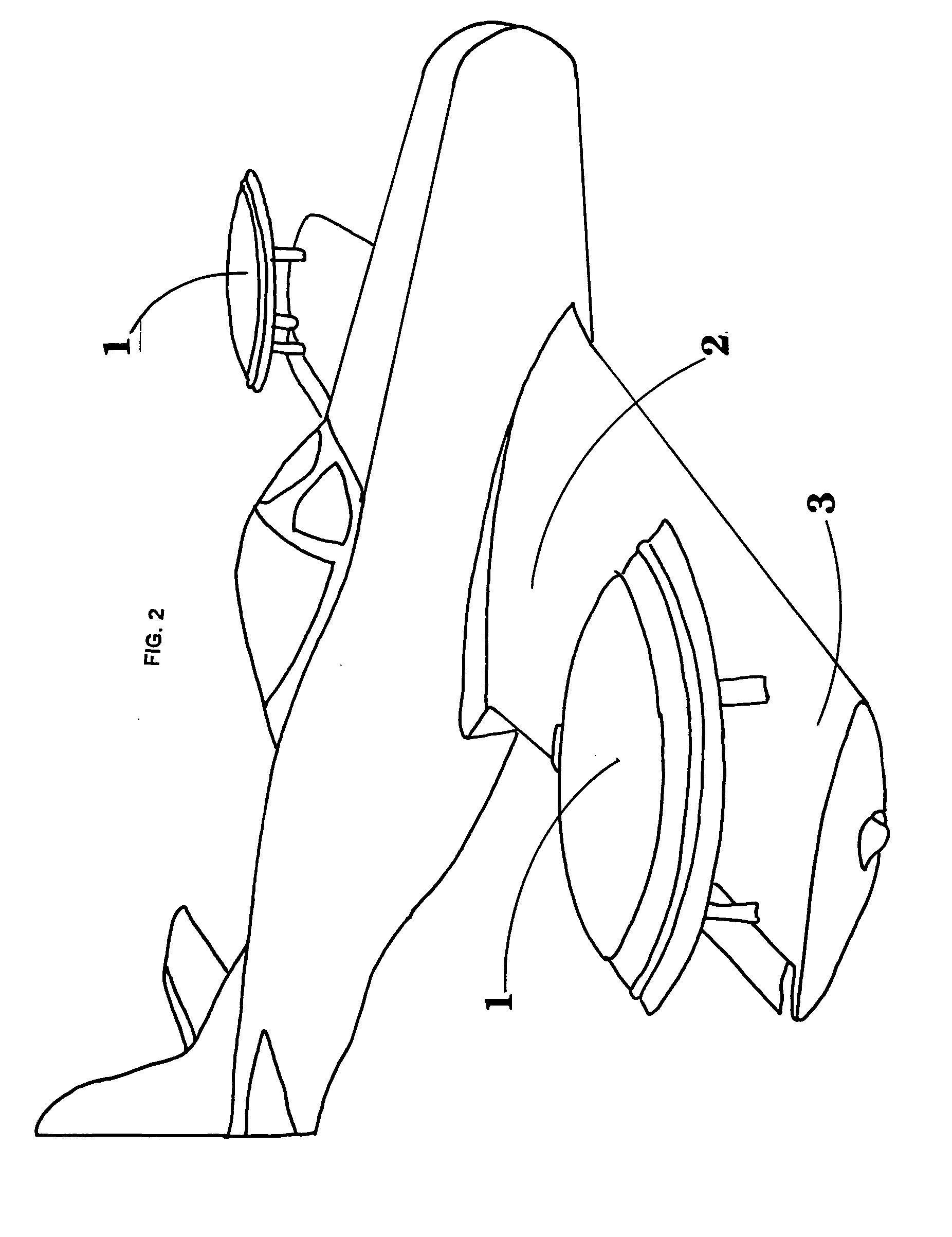
[0024]The present invention is illustrated in the referred embodiment in FIG. 1 which depicts a portion of an aircraft airfoil 3 with an oval diskette 1 with the longest length of the diskette pointed toward the air flow direction and the shorter width of the oval diskette is perpendicular to the wing root of the airfoil. The oval diskette is best sited above the airfoil at no greater height than ½ of the width of the oval diskette and the angle of attack of the oval diskette is set between zero and seven degrees of incident to the main airfoil cord. The length of the oval diskette is at a preferred length of the cord of the airfoil that the oval diskette is placed above. The profile of the oval diskettes are thick with a continues leading edge and have no bias along the oval edge as to where lift can develop. The ovals are none moving but the supports are adjustable for Angle of Attack selection.

[0025]If more than one oval diskette are installed on a aircraft wing or airfoil as see...


PUM


Abstract

A wing assembly has a wing and one or more no-bias laminar flow oval diskettes that are fixed on a support structure along the C/L (center of lift) of an airfoil, of an aircraft wing. The benefit of an oval diskette with laminar flow is that it has no speed limitations and it allows an aircraft to clime at a speed that matches its Ground Effect Lift speed which is a 25% performance increase and a 40% reduction in vortex drag with a increase stability that eliminates inertia coupling of high-speed airfoils.

Description

REFERENCE TO RELATED APPLICATION[0001]This application claims the benefit of U.S. Provisional Application No. 61 / 342,937, filed Apr. 22, 2010.BACKGROUND OF INVENTION[0002]1. Field of the Invention[0003]The invention relates to an aircraft wing or a airfoil used to increase the lifting capacity and improve flight performance of an aircraft in takeoff, clime, cruse, and landing with the addition of two or more oval diskettes designed to employ laminar flow technology that will increase lift without additional drag due to wetted area.[0004]2. Discussion of Prior Art.[0005]A wing that is high lift is also high drag and to date to have a wing perform at high cruse speed but still provide adequate lift for safe operations at takeoff and landing, a number of slats on the leading edge and a number of flaps on the trailing edge have been employed to give a overall solution to the high lift / high drag problem. Nowak with U.S. Pat. No. 5,772,155, Jun. 30,1998 and Oulton with U.S. Pat. No. 3,776...

Claims


Application Information

Patent Timeline
Patent Type & Authority Applications(United States)
IPC IPC(8): B64C23/00B64C3/36B64C3/00
CPCY02T50/166B64C23/005Y02T50/10
Inventor HAMILTON, TERRY WAYNE
Owner HAMILTON TERRY WAYNE
Why Eureka
Try Eureka