
Agricultural implement tool frame actuating system

a tool frame and actuating system technology, applied in the direction of harrows, spades, ploughs, etc., can solve the problems of undesirable seed deposition depth and tool frame rotation

Active Publication Date: 2011-11-24
CNH IND CANADA
View PDF14 Cites 43 Cited by
  • Summary
  • Abstract
  • Description
  • Claims
  • Application Information

AI Technical Summary

Benefits of technology

[0003]Embodiments of the present disclosure include a frame actuator configured to transfer weight from a tool bar to a tool frame while the tool frame is in a lowered position, and to raise the tool frame into a transport position. In one embodiment, an agricultural implement includes a tool bar and a tool frame rotatably coupled to the tool bar. The agricultural implement also includes multiple row units coupled to the tool frame, and a frame actuator extending between the tool bar and the tool frame. The frame actuator is configured to rotate the tool frame between a lowered position that places each row unit in contact with soil and a transport position that raises each row unit above the soil. The frame actuator is also configured to transfer weight from the tool bar to the tool frame while the tool frame is in the lowered position. Each row unit includes a ground engaging tool configured to selectively engage and disengage the soil while the tool frame is in the lowered position. Transferring weight from the tool bar to the tool frame urges the row units against the soil despite variations in soil elevation and / or torque induced by a draft force acting on the ground engaging tools. Consequently, the ground engaging tools may maintain a desired penetration depth into the soil during seeding and / or planting operations.

Problems solved by technology

Unfortunately, a draft force associated with pulling the row units through the soil may induce a torque that drives the tool frames to rotate upwardly.
The upward rotation of the tool frames may reduce a penetration depth of ground engaging tools of the row units, resulting in undesirable seed deposition depths.

Method used


Image

  • Agricultural implement tool frame actuating system
  • Agricultural implement tool frame actuating system
  • Agricultural implement tool frame actuating system

Examples


Embodiment Construction

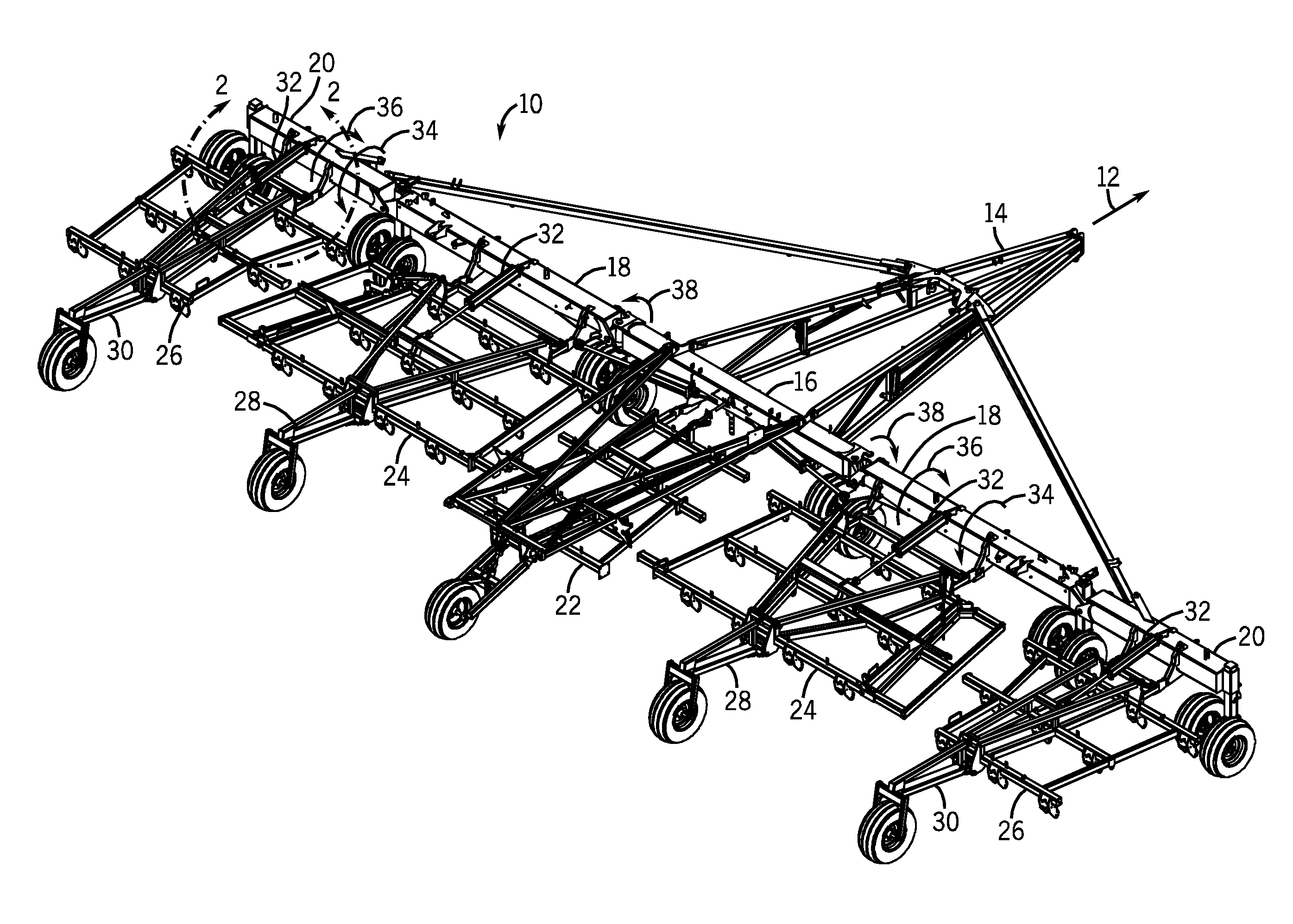
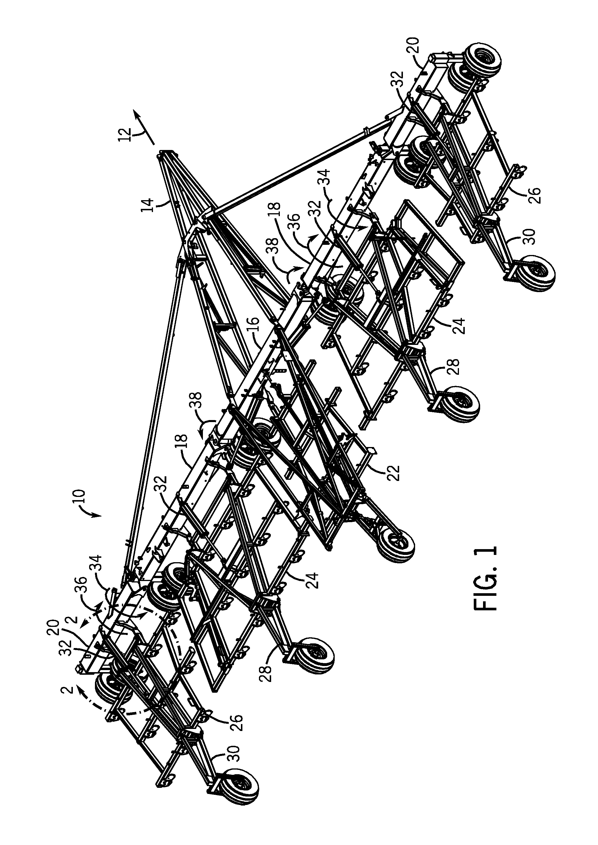
[0010]Turning now to the figures, FIG. 1 is a perspective view of a folding implement 10 in a working position. The implement 10 is designed to be towed behind a work vehicle such as a tractor along a direction of travel 12. The implement 10 includes a tow bar assembly 14 which is shown in the form of an A-frame hitch assembly. The tow bar assembly 14 may include a hitch used to attach to an appropriate tractor hitch via a ball, clevis, or other coupling. The tow bar assembly 14 is coupled to a central tool bar 16, and two first wing tool bars 18 are each coupled to an end of the central tool bar 16. In addition, a second wing tool bar 20 is coupled to each first wing tool bar 18. As illustrated, both the first wing tool bars 18 and the second wing tool bars 20 are substantially aligned with the longitudinal axis of the central tool bar 16. In other words, each tool bar 16, 18 and 20 is positioned perpendicular to the tow bar assembly 14. In alternative embodiments, the central tool...


PUM


Abstract

In an embodiment, an agricultural implement includes a tool bar and a tool frame rotatably coupled to the tool bar. The agricultural implement also includes multiple row units coupled to the tool frame, and a frame actuator extending between the tool bar and the tool frame. The frame actuator is configured to rotate the tool frame between a lowered position that places each row unit in contact with soil and a transport position that raises each row unit above the soil. The frame actuator is also configured to transfer weight from the tool bar to the tool frame while the tool frame is in the lowered position. Each row unit includes a ground engaging tool configured to selectively engage and disengage the soil while the tool frame is in the lowered position.

Description

BACKGROUND[0001]The invention relates generally to a system for actuating a tool frame on an agricultural implement, and more specifically, to a frame actuator configured to transfer weight from a tool bar to the tool frame while the tool frame is in a lowered position, and to raise the tool frame into a transport position.[0002]A range of agricultural implements have been developed and are presently in use for tilling, planting, harvesting, and so forth. Seeders, for example, are commonly towed behind tractors and may cover wide swaths of ground which may be tilled or untilled. Such devices typically open the soil, dispense seeds in the soil opening, and re-close the soil in a single operation. In seeders, seeds are commonly dispensed from bulk seed tanks and distributed to row units by a distribution system. To make the planting operation as efficient as possible, very wide swaths of ground may be covered by extending wings on either side of a central boom section of the implement...

Claims


Application Information

Patent Timeline
IPC IPC(8): A01B63/24A01B63/30A01B63/32A01B73/02
CPCA01B63/32A01B73/06A01B73/048
Inventor FRIGGSTAD, TERRANCE A.RYDER, NICHOLAS GEORGE ALFREDYUEN, CORY ADRIAN
Owner CNH IND CANADA
Features
  • Generate Ideas
  • Intellectual Property
  • Life Sciences
  • Materials
  • Tech Scout
  • Unparalleled Data Quality
  • Higher Quality Content
  • 60% Fewer Hallucinations
Learn More