Adjustable orbit imbalance compensating orbital shaker

a technology of orbital shaker and orbital imbalance, which is applied in the direction of chemistry apparatus and processes, mixers, mixing, etc., can solve the problems of unsatisfactory turbulence or splashing, base unit movement or “walking”, and undesirable effect of increasing overall weight, so as to reduce static imbalance and minimize the effect of imbalan

Active Publication Date: 2011-11-24
EPPENDORF INC
View PDF13 Cites 30 Cited by
  • Summary
  • Abstract
  • Description
  • Claims
  • Application Information

AI Technical Summary

Benefits of technology

[0020]In another aspect of the invention, these features allow the user to adjust the position of the counterweights in response to the noticeable imbalance of the system or information provided by the orbital shaker controller to minimize the static imbalance or reduce it to an acceptable level.
[0021]Additionally, a sliding connection placed between the mounting portions of the first and second shafts allows adjustment of the eccentric orbit by moving the shaft axes relative to each other.

Problems solved by technology

The forces resulting from the total orbitally-rotating mass can often cause motion of the base of the shaker which can superimpose additional motion components into the liquid in the vessels and lead to undesirable turbulence or splashing.
These forces can also cause the base unit to move or “walk” along its support surface.
This leads to the undesirable effect of increasing the overall weight of the shaker simply to address for stabilization.
These arrangements all undesirably require selecting specific masses and locations, vertically as well as radially, which vary depending upon the platform load conditions.
In addition, in order to correct for large mass imbalances statically and dynamically, these devices require considerable space to place the correcting weights in the appropriate locations relative to the platform load, and also increase the overall product weight.
This is a practical solution for modest platform loads but is not feasible for providing a large dynamic compensation range.
For example, if a large counterweight mass is selected, it may not be positioned close enough to the axis of rotation to achieve a minimal balance compensation.
If a small counterweight is selected, it is difficult to position it far enough from the axis of rotation to balance a large platform load without using considerable additional space.
Also, this device does not provide any feedback to the user that the onset of detrimental instability is imminent, which would require a compensating adjustment.
US2008 / 0056059 to Manera, et al. describes the use of a vibration sensor to detect an unbalanced loading condition and reduce the shaking speed to a stable magnitude, but it does not provide a means for the counterweight of the orbital shaker to be adjusted, or a process which can be applied, in order to achieve the desired speed.
This fluid generates a variable imbalance depending upon the geometry of the container, amount of fluid in the container, the orbit diameter of the shaker, and the speed of the shaker which could result in a different amount of resultant balance compensation depending upon the operating conditions.
Furthermore, automatic balancing techniques, whereby balancing masses migrate to the correct positions to minimize vibrations, are not generally applicable to orbital shakers because orbital shakers operate much slower than the critical speeds required to enable these techniques.
This radius is not adjustable.
What has not been achieved is a means of manually or automatically adjusting the eccentric throw within a continuously variable range.
Furthermore, a change in the eccentric throw for a given platform load results in a change in the amount of counterweight needed to compensate for it.

Method used


Image

  • Adjustable orbit imbalance compensating orbital shaker
  • Adjustable orbit imbalance compensating orbital shaker
  • Adjustable orbit imbalance compensating orbital shaker

Examples


Embodiment Construction

[0042]The description of the present invention has been presented for purposes of illustration and description, but is not intended to be exhaustive or limited to the invention in the form disclosed. Many modifications and variations will be apparent to those of ordinary skill in the art without departing from the scope and spirit of the invention.

[0043]During the course of this description like numbers will be used to identify like elements according to the different views which illustrate the invention.

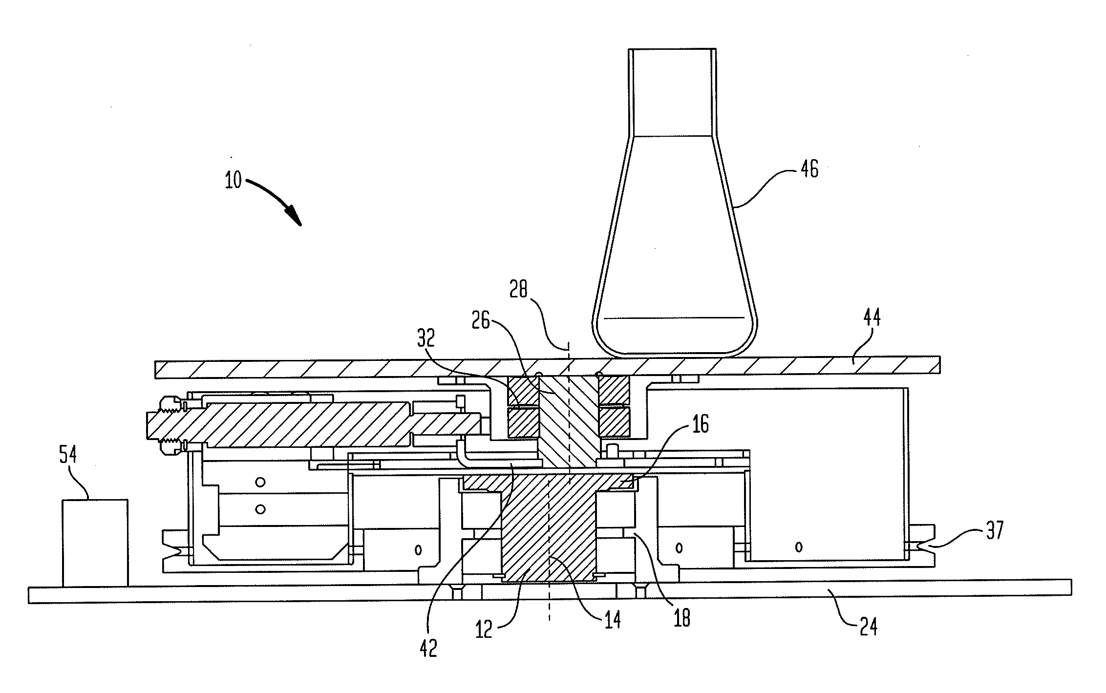
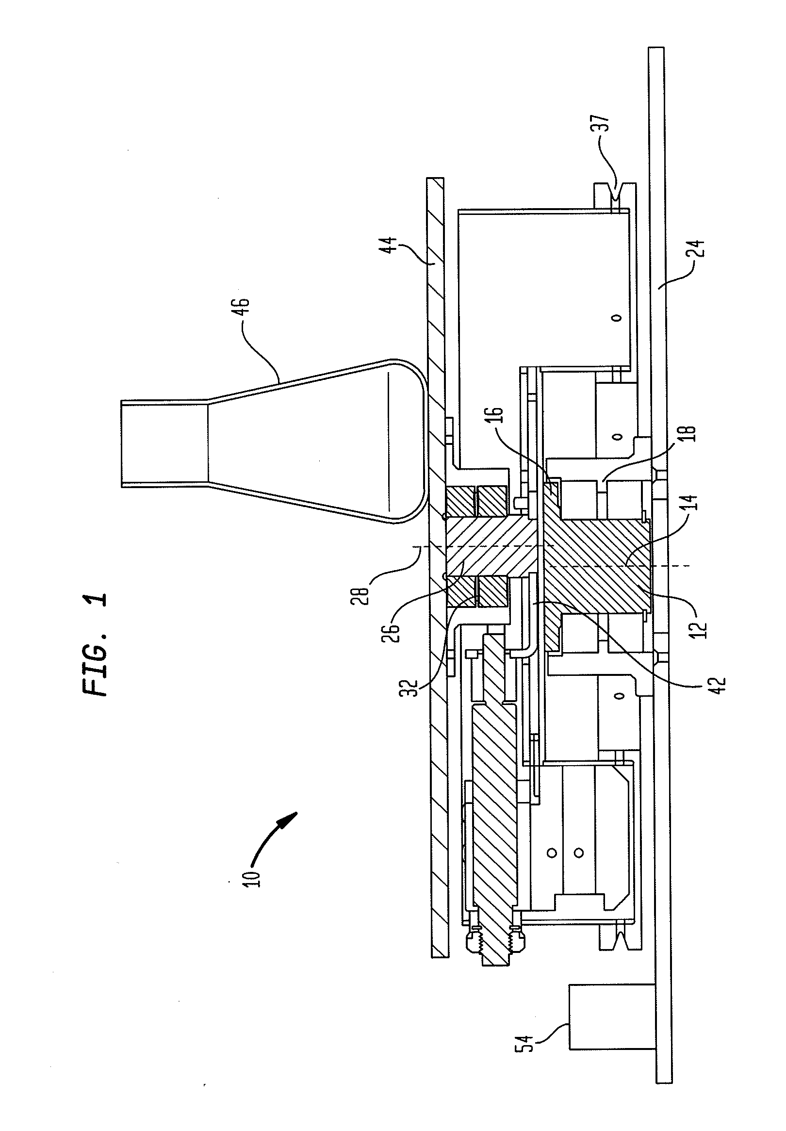
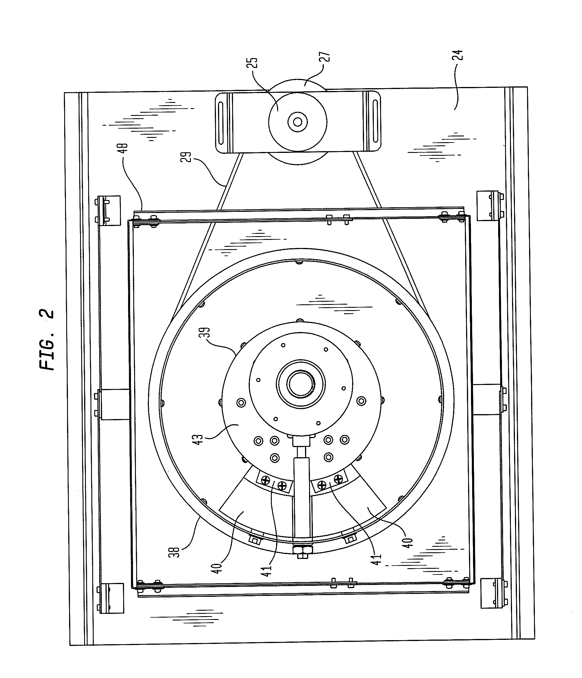
[0044]The present invention advantageously provides an orbital shaker device with the ability to adjust the eccentric throw and to adjust the compensating counterweights simultaneously.

[0045]The present invention also advantageously provides an orbital shaker device that provides feedback to the user, or, in the case of a shaker with automatic adjustment, that provides feedback to it's controller that the onset of detrimental instability which would require a compensating adjustment...


PUM


Abstract

An orbital shaker apparatus is provided, including a first shaft connected to a first bearing assembly at a first end and a mounting portion at the other. The first shaft is rotatable about a first shaft axis, and is connected to a motor. The second shaft has a bearing assembly on the mounting portion at one end and a platform at the other, and is aligned parallel to and offset from the first shaft by a distance. A counterweight rotor assembly is coupled to the mounting portion, and rotated by a belt driven by a pulley connected to the rotating shaft of a counterweight motor. The counterweight assembly includes two counterweight bearings, each having a counterweight wedge. The platform also includes supports for objects to be secured thereto. In use, as the counterweight rotor rotates, the second shaft, second bearing assembly, and platform describes a circular orbit with diameter 2R.

Description

CROSS-REFERENCE TO RELATED APPLICATIONS[0001]This application claims priority from U.S. Provisional Patent Application No. 61 / 347,484 filed on May 24, 2010 by Zamirowski, et al. titled “ADJUSTABLE ORBIT IMBALANCE COMPENSATING ORBITAL SHAKER,” which is incorporated herein by reference in its entirety.BACKGROUND OF THE INVENTION[0002]1. Statement of the Technical Field[0003]This invention generally relates to orbital shaker apparatus and, more specifically, to an apparatus for reducing the instability generally caused by static imbalance between a counterweight and the load of flasks or other vessels on the platform, and an apparatus for varying the orbit diameter of the shaker.[0004]2. Description of the Related Art[0005]An orbital shaker apparatus is a mixing or stirring device used especially in scientific applications or mixing or stirring containers, such as beakers and flasks holding various liquids on a platform. Specifically, an orbital shaker translates a platform in a manner...

Claims


Application Information

Patent Timeline
Patent Type & Authority Applications(United States)
IPC IPC(8): B01F11/00
CPCB01F11/0014B01F31/22
Inventor ZAMIROWSKI, ERIKJOSHI, ASHVINKOEHN, HEINZ G.JOHNSON, JOEL
Owner EPPENDORF INC
Why Eureka
Try Eureka