Interleaver device and receiver for a signal generated by the interleaver device

Inactive Publication Date: 2011-11-24
FRAUNHOFER GESELLSCHAFT ZUR FOERDERUNG DER ANGEWANDTEN FORSCHUNG EV
View PDF3 Cites 20 Cited by
  • Summary
  • Abstract
  • Description
  • Claims
  • Application Information

AI Technical Summary

Benefits of technology

[0035]According to another embodiment, a method of receiving a receive signal having first and second interleaved code words, the first interleaved code word having a sequence of first interleaver units interleaved in accordance with a first convolutional interleaver specification, which first interleaver units belong to a first transport channel, and the second interleaved code word having a sequence of second interleaver units interleaved in accordance with a second convolutional interleaver specification, which second interleaver units belong to a second transport channel, the second convolutional interleaver specification being derived from the first convolutional interleaver specification, and the interleaved first transport channel and the interleaved second transport channel being mutually interleaved, in accordance with the first or second convolutional interleaver specification, such that a receiver configured to receive the first transport channel and not configured to receive the second transport channel may correctly receive and decode the first transport channel despite the presence of the second transport channel may have the steps of providing de-interleaver information with which first and second de-interleaver specifications may be determined; and altering the sequence of the second interleaver units in the multiplex signal in accordance with the second de-interleaver specification, which is derived from the first convolutional interleaver specification and is inverse to the second convolutional interleaver specification, so as to acquire a de-interleaved second code word, such that the second transport channel may be correctly received and decoded.
[0037]The finding of the present invention is that backward compatibility is achieved in that an existing first transport channel interleaved by means of a first interleaver specification has a second interleaved transport channel added to it which is interleaved by means of a second interleaver specification derived from the first interleaver specification, such that transmission resources defined by the first and second interleaver specifications are matched to each other such that joint transmission of the first and second interleaved transport channels via a joint transmission channel does not lead to any conflicts or collisions at all. For this purpose, an original data rate of the first transport channel is naturally reduced so as to free transmission resources for the second transport channel. By the second interleaver specification, which is cleverly derived, the transmission resources that have been freed up are now assigned to the second transport channel in a collision-free manner.

Problems solved by technology

However, signal delays only play a minor role.
Some data services (e.g. software update of a navigation device) tolerate a very long delay and need to be provided with only little robust protection (an error protection code on a higher transmission layer will see to this).
The disadvantage of this approach is that it cannot be used for existing systems having a first transport channel that is read out from the output of an interleaver device within the transmitter and is then transmitted, and wherein transmission resources of the first transport channel are taken over by a second transport channel without the receiver having to be informed about this in order to de-interleave and decode the first transport channel.
However, they currently cannot make any use of data from telephone connections, for example.
Said receiver will not be able to correctly decode interleaver units of the second transport channel, and it will therefore output an error, such that the second transport channel will be recognized as an error and be discarded by the existing receiver.

Method used


Image

  • Interleaver device and receiver for a signal generated by the interleaver device
  • Interleaver device and receiver for a signal generated by the interleaver device
  • Interleaver device and receiver for a signal generated by the interleaver device

Examples


Embodiment Construction

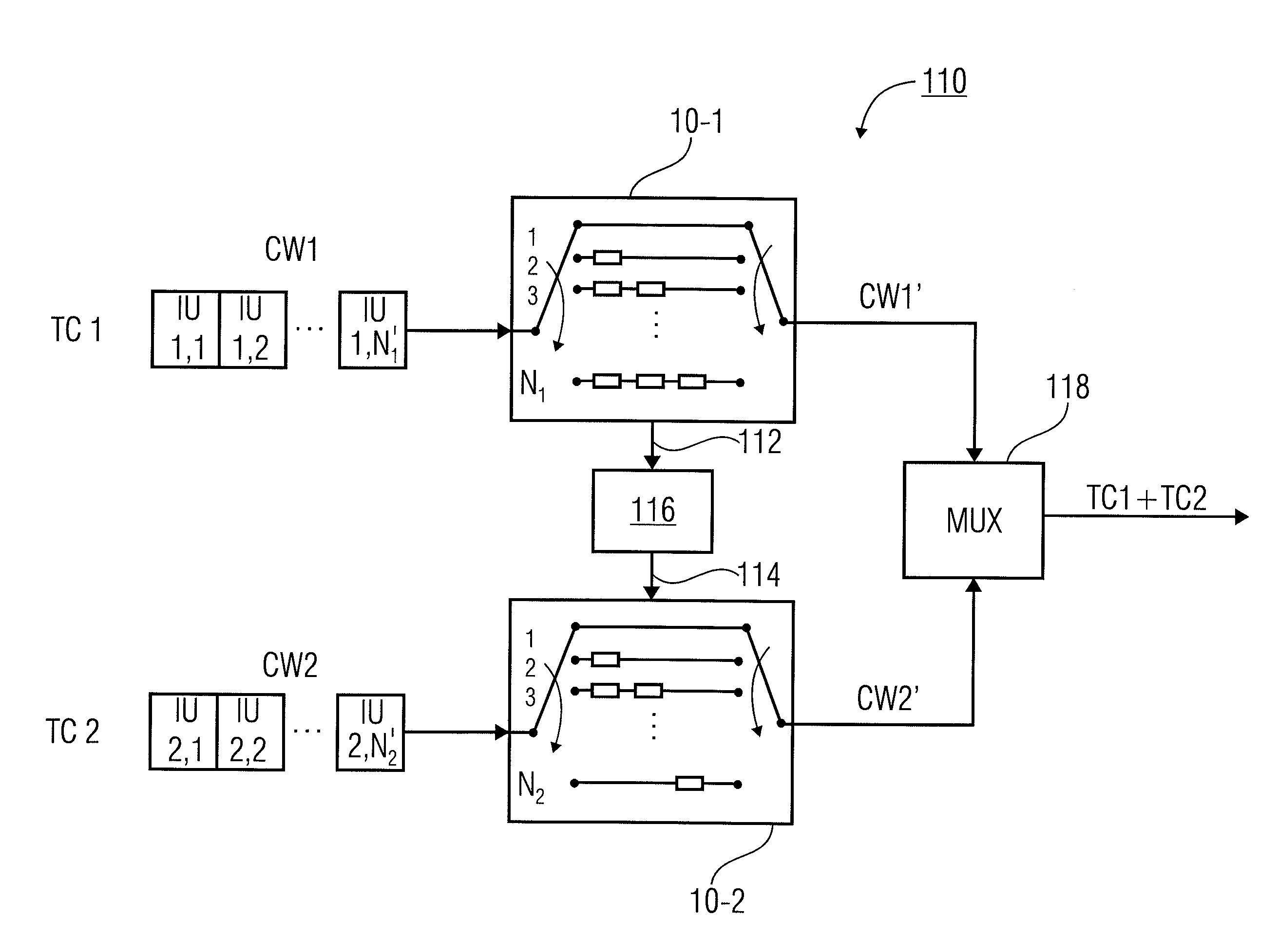
[0060]In addition, embodiments of the present invention comprise an interleaver device for joint transmission of first and second transport channels via a transmission channel, the first transport channel comprising a sequence of first interleaver units, and the second transport channel comprising a sequence of second interleaver units, each interleaver unit comprising at least one symbol. The interleaver device comprises a first interleaver means for altering the sequence of the first interleaver units in accordance with a first interleaver specification, defining first transmission resources for joint transmission, so as to obtain an interleaved first transport channel comprising an altered sequence of first interleaver units. In addition, the interleaver device comprises a second interleaver means for altering the sequence of the second interleaver units in accordance with a second interleaver specification defining second transmission resources for joint transmission, so as to o...


PUM


Abstract

The inventive concept enables backward-compatible extension of existing interleaver-based transmission systems to the effect that in addition to an existing logical transport channel, which is interleaved using a standardized interleaver profile, further logical transport channels may be transmitted via the same physical transmission channel. In this context, the first transport channel obviously is reduced in terms of data rate, so that the additional transport channels may actually obtain a transmission capacity that is needed accordingly. Interleaver profiles of the further logical transport channels are derived, to this end, from the interleaver profile of the first transport channel.

Description

CROSS-REFERENCE TO RELATED APPLICATIONS[0001]This application is a continuation of copending International Application No. PCT / EP2009 / 067538, filed Dec. 18, 2009, which is incorporated herein by reference in its entirety, and additionally claims priority from German Application No. DE 10 2008 062 808.5-31, filed Dec. 23, 2008, which is incorporated herein by reference in its entirety.BACKGROUND OF THE INVENTION[0002]The present invention relates to digital transmission technology and, in particular, to transmission concepts particularly well suited for time-varying transmission channels as may be encountered in mobile radio and broadcasting, and wherein several data types (e.g. audio, video) are to be transmitted via a single signal.[0003]Time and / or frequency interleaving, combined with so-called forward error correction methods (FEC methods), is part of a basic principle in transmission technology. Such interleaving is also employed in digital video broadcasting (DVB), for example...

Claims


Application Information

Patent Timeline
IPC IPC(8): H03M13/27G06F11/10
CPCH03M13/2732H04L1/0071H03M13/6508H03M13/2707
Inventor BREILING, MARCOEBERLEIN, ERNSTHILDINGER, RAINERSTADALI, HOLGERVARGAS BARROSO, AHARON JESUS
Owner FRAUNHOFER GESELLSCHAFT ZUR FOERDERUNG DER ANGEWANDTEN FORSCHUNG EV
Why Eureka
Try Eureka