Functional shoe

Inactive Publication Date: 2011-12-01
FOOT BALANCE
View PDF21 Cites 29 Cited by
  • Summary
  • Abstract
  • Description
  • Claims
  • Application Information

AI Technical Summary

Benefits of technology

[0010]An object of the present invention is to provide a sho

Problems solved by technology

However, typical shoes employ flat soles that are prohibitive of the 3-step walking method, so that body weight-induced impacts are relayed to the spine and other body parts while walking, stressing the torso, shoulders, neck, etc., causing not only discomfort or pain, but also deformation of toes and progression toward flat-footedness from deficient support of foot joints, and are thus manifested with a wide array of intrinsic lim

Method used


Image

  • Functional shoe
  • Functional shoe
  • Functional shoe

Examples


first embodiment

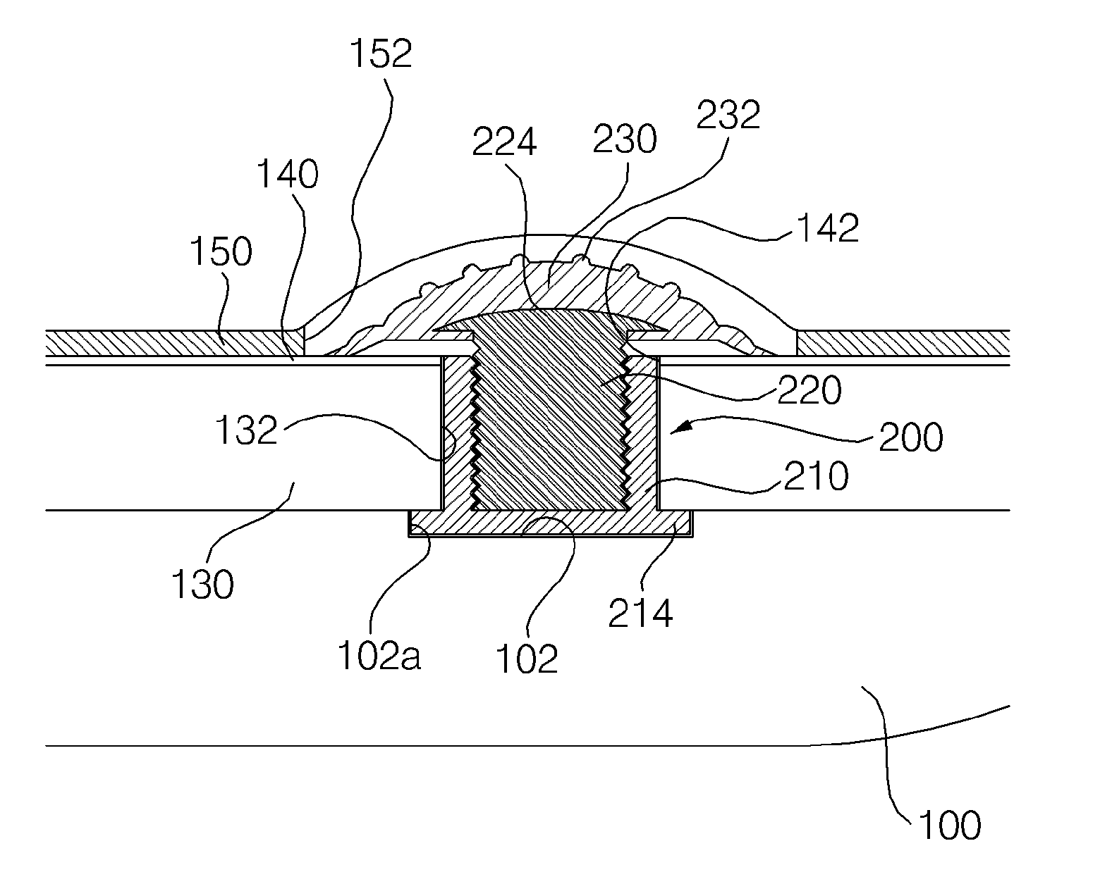
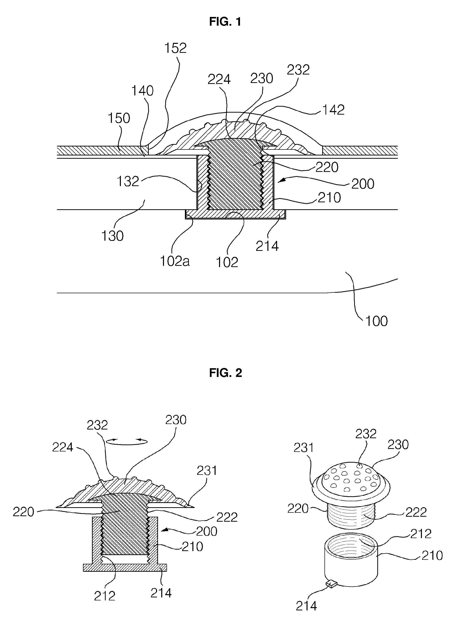
[0027]FIG. 1 is a sectional view showing an arch support applied to a shoe having functionality according to a first embodiment of the present invention.

[0028]Referring to FIG. 1, an outsole 100 is disposed at the bottom, and a midsole 130, an insole board 140, and an insole 150 are stacked on the outsole 100.

[0029]According to the present invention, receptacles 142, 132, and 102 are defined corresponding to a wearer's foot arch and communicate the insole board 140 with the midsole 130 and the outsole 100, and an arch support 200 is inserted sequentially into the receptacles 142, 132, and 102.

[0030]An opening 152 is defined in a portion of the insole 150 that is disposed uppermost to correspond to the arch support 200, and a contacting member 230 of the arch support 200 may be exposed. Alternatively, an opening may not be defined to provide a tidier exterior. In the latter case, the portion of the insole 150 corresponding to the contacting member 230 of the arch support 200 may be t...

second embodiment

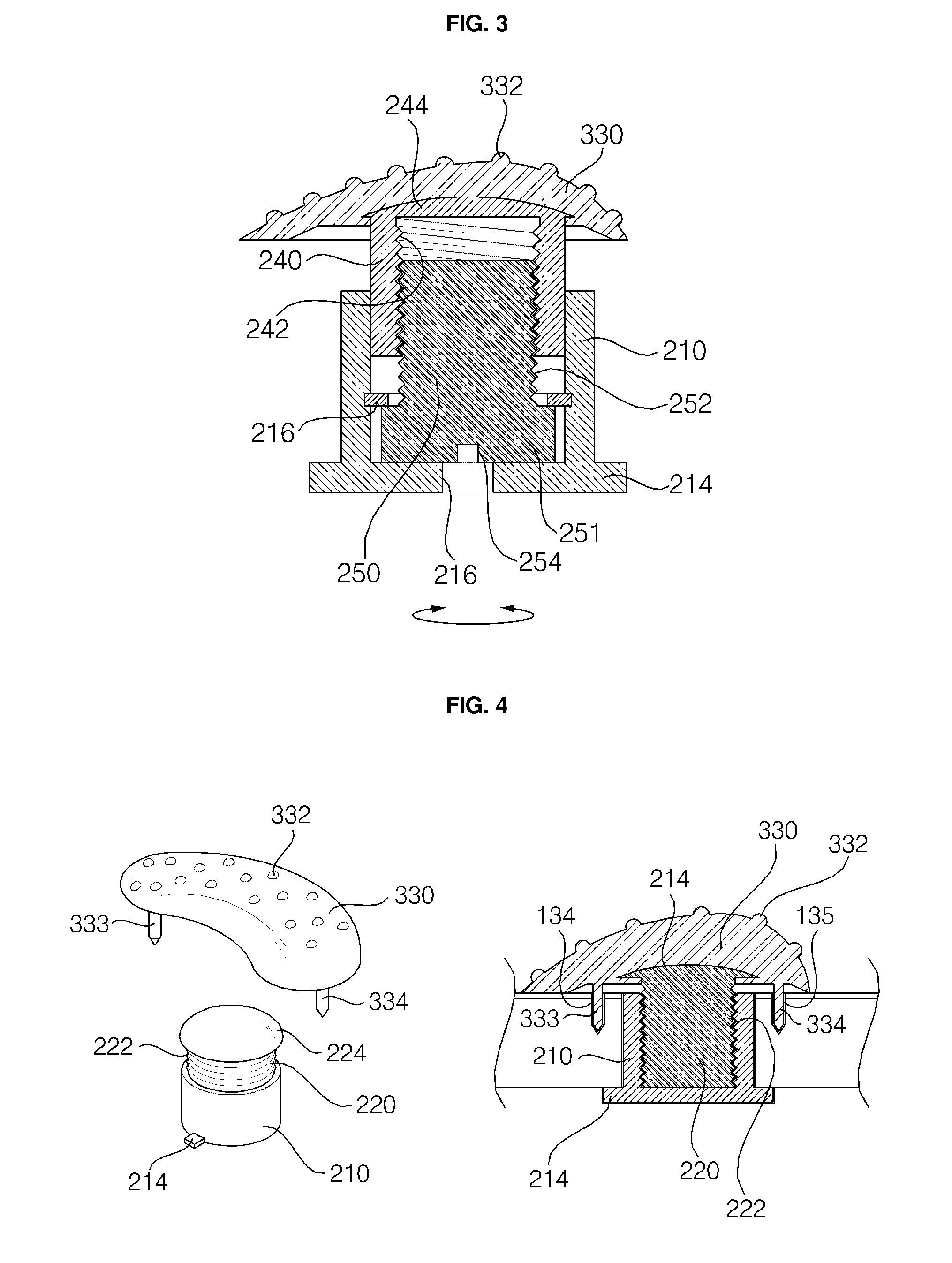
[0042]FIG. 3 a sectional view of an arch support according to a second embodiment of the present invention.

[0043]The second embodiment may be applied when performing height adjustment by rotating a contacting member 330 itself proves difficult.

[0044]Referring to FIG. 3, an insert 240 is coupled to a surface of a contacting member 330 having a shape (refer to FIG. 4) similar to an actual foot arch. The insert 240 is cylindrical with screw threads 242 defined in the inside of its sidewall, and has a head 244 at an upper portion thereof that is coupled and fixed to the contacting member 330.

[0045]A bolt 250 is inserted and screw-coupled in the insert 240, a slot 254 is defined in the head 251 of the bolt 250 so that the bolt 250 may be rotated using the slot 254, and screw threads 252 of the bolt 250 and screw threads 242 of the insert 240 are screw-coupled to raise the insert 240.

[0046]A through-hole 216 is defined in the center of the undersurface of the housing 210 corresponding to ...

third embodiment

[0050]FIG. 4 shows an arch support according to a third embodiment of the present invention, each of which a perspective view and a sectional view.

[0051]This embodiment, like the second embodiment, may be applied in cases where rotating the contacting member 330 itself for height adjustment proves difficult.

[0052]Referring to FIG. 4, a pair of supporting rods 333 and 334 is formed on the reverse surface of the contacting member 330 having a shape similar to an actual foot arch. The distance between the rods 333 and 334 may be greater than the diameter of the housing 210.

[0053]According to the present embodiment, guide holes 134 and 135 are defined in the midsole 130, in which the supporting rods 333 and 334 are inserted.

[0054]As in the first embodiment, the insert 220 is cylindrical and has an approximately semispherical head 224 integrally formed with the top of the insert 220 and is separably coupled to the contacting member 330.

[0055]To describe the operation of the above-structu...


PUM


Abstract

Disclosed is a functional shoe, comprising a foot arch support, wherein said foot arch support includes a support body accommodated and fixed in a shoe body, a slider tightened to the support body by a screw, and a contact member which is coupled to the top of the slider and projects toward the inside of the shoe to contact the arch of the foot. The slider moves in the upward and downward directions by means of the rotation of the contact member.

Description

REFERENCE TO RELATED APPLICATIONS[0001]This is a continuation of pending International Patent Application PCT / KR2010 / 000815 filed on Feb. 10, 2010, which designates the United States and claims priority of Korean Patent Application No. 10-2009-0011039 filed on Feb. 11, 2009, the entire contents of which are incorporated herein by reference.FIELD OF THE INVENTION[0002]The present invention relates to a shoe having functionality, and more particularly, to a shoe having the functionality of a height-adjustable arch support.BACKGROUND OF THE INVENTION[0003]One of the general functions of shoes is alleviating stress relayed to the spine and other body parts from body weight-induced impacts while walking.[0004]So-called “3-step” walking is a well-known, purportedly optimal walking method that involves stepping on the ground in the sequence of heel-sole-toes and moving forward.[0005]However, typical shoes employ flat soles that are prohibitive of the 3-step walking method, so that body wei...

Claims


Application Information

Patent Timeline
IPC IPC(8): A43B7/22
CPCA43B7/142A43B7/22A43B7/1465A43B7/146A43B7/1464
Inventor JUNG, HYUN-YOUNGKIM, JONG-KOOK
Owner FOOT BALANCE
Why Eureka
Try Eureka