Sandal with pneumatic support

a technology of pneumatic support and sandal, applied in the field of open shoes or sandals, can solve the problems of increasing affecting the comfort of the foot, and reducing the support ability and strength of the foot, so as to improve the grip, reduce the space between the straps and the sole, and increase the thickness

Active Publication Date: 2016-10-18
DIMATTEO VITO E
View PDF38 Cites 14 Cited by
  • Summary
  • Abstract
  • Description
  • Claims
  • Application Information

AI Technical Summary

Benefits of technology

[0012]In yet another embodiment, additional air bladders are placed within the straps that extend from the top of the toe divider over the foot. These air bladders distend the straps to increase their thickness, thereby reducing the space between the straps and the sole to provide a better grip for increased security of the sandal on the foot. The strap bladders preferably communicate with the single air pump at the top of the toe divider and with the relief valve and sole bladder to simplify construction and reduce the number of components.

Problems solved by technology

This early footwear amounted to little more than a means of securing a sheet of protective material beneath the sole of the foot, and thus provided no additional arch or other support.
As a result, the foot becomes accustomed to such support, and the tendon and muscle structure of the foot may lose much of its supportive ability and strength.
This may not be of any great consequence so long as shoes providing the proper support are worn, but such is not always the case.
As a result, people who habitually wear such inexpensive footwear during most of the day for months at a time during the warm season may experience various problems due to the lack of arch support provided by such footwear.
The lack of proper arch support often results in subconscious adjustments to the posture, with the muscular structure of the legs, hips, and lower back being unaccustomed to such changes.
This can result in various muscle aches and pains, strained tendons, plantar fasciitis, and other physical problems to the feet, legs, hips, and lower back, with the problems requiring costly and time-consuming treatment to rectify.

Method used


Image

  • Sandal with pneumatic support
  • Sandal with pneumatic support
  • Sandal with pneumatic support

Examples


first embodiment

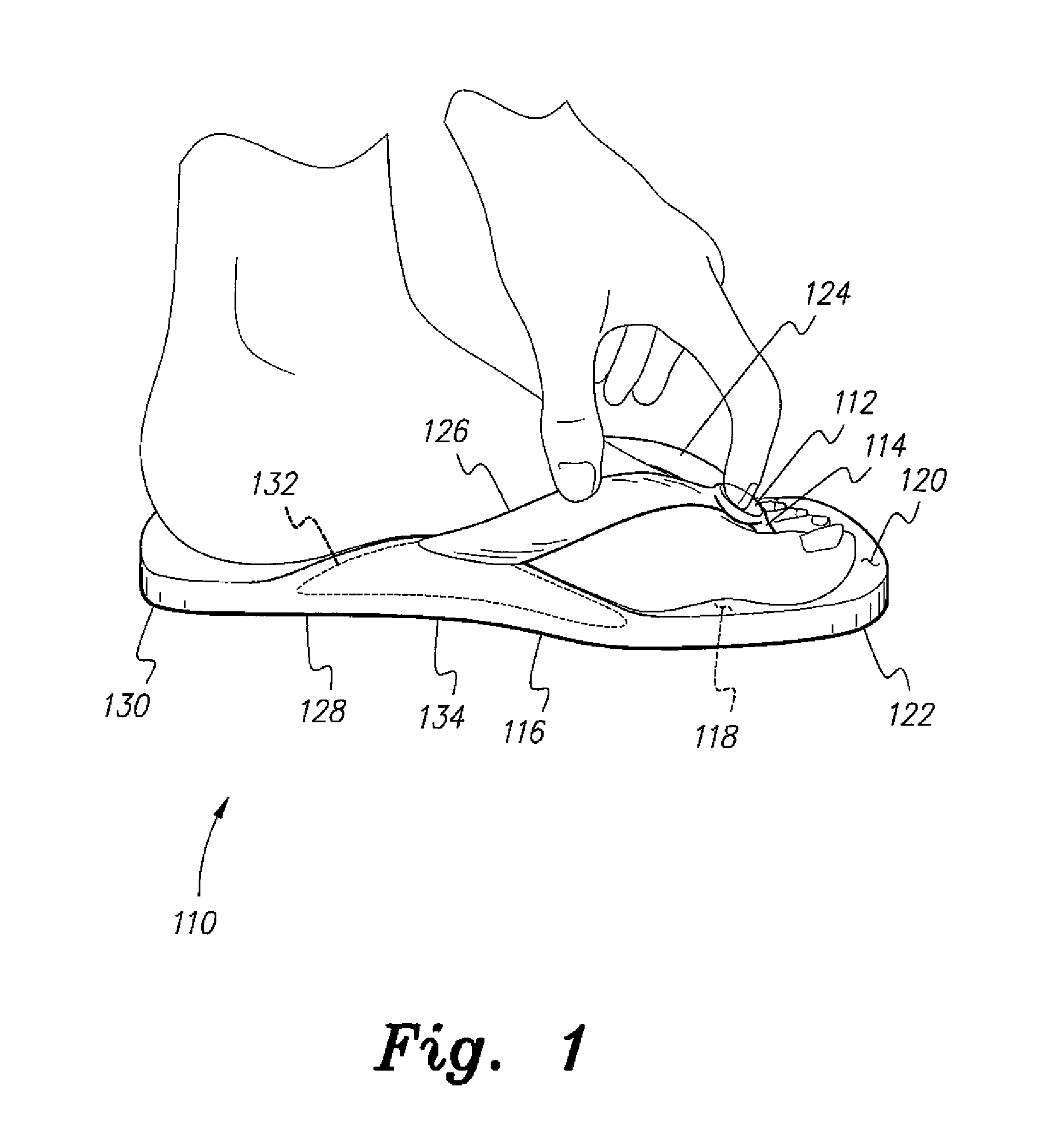
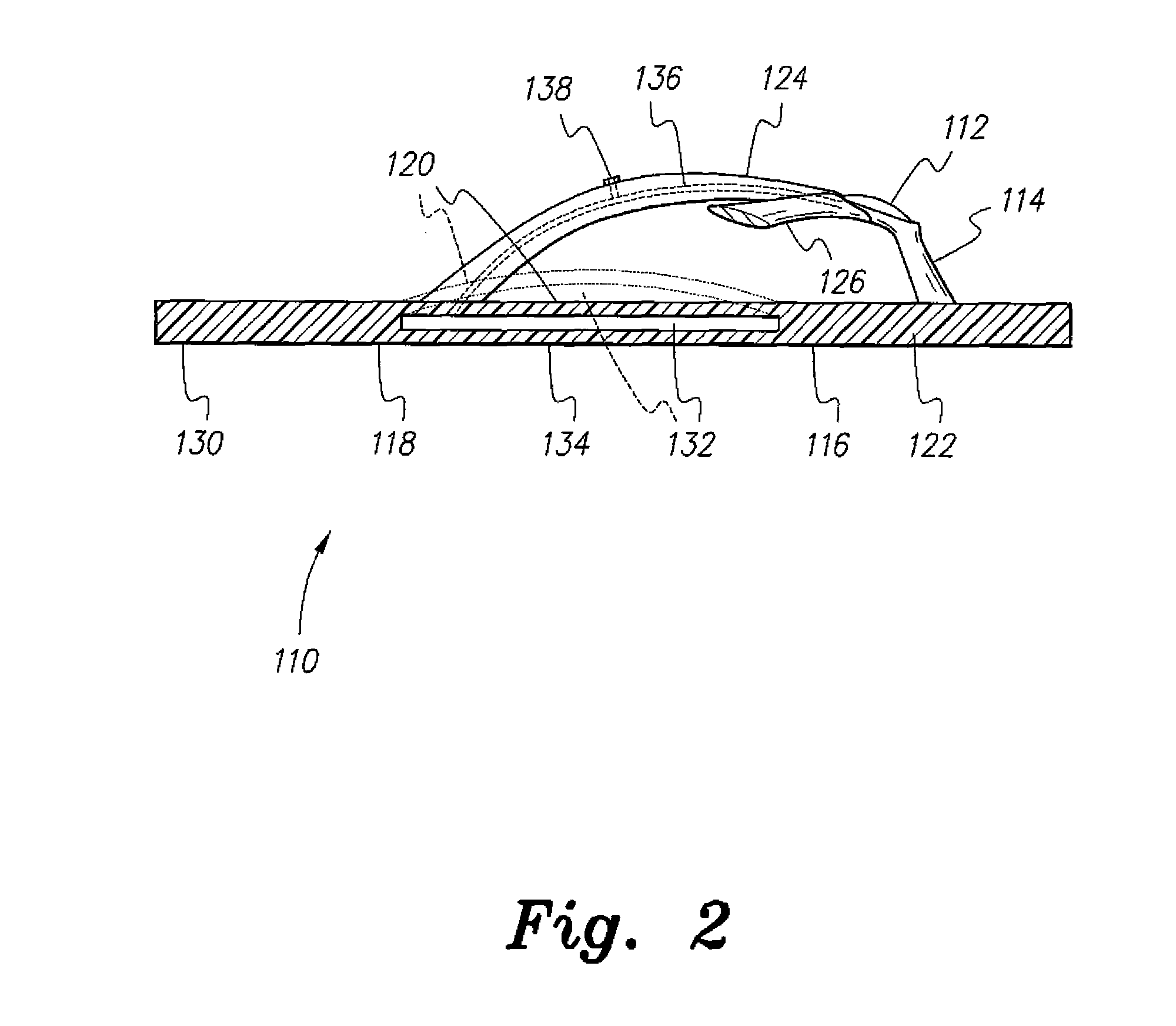
[0024]FIGS. 1 and 2 of the drawings illustrate a sandal with pneumatic support, designated generally as 110 in the drawings, which is a flip-flop sandal having a small, manually actuated air pump 112 permanently affixed atop the toe divider 114 of the sandal, and integrally formed therewith. The flat sole 116 is devoid of supportive contour for the foot, other than the pneumatic arch support. The sole 116 has a lower surface 118, an upper surface 120 parallel thereto, and a core 122 therebetween, and may be formed of leather, foam or other resilient plastic material, or other suitable material. Opposite first and second foot-securing straps 124 and 126 extend from the top of the toe divider 114 rearward to opposite points along the rearward periphery 128 of the sole 116 near the heel portion 130 thereof.

[0025]The sole 116 includes a pneumatically inflatable bladder 132 disposed within the core 122 between the upper and lower surfaces 118 and 120, in the arch portion 134 of the sole ...

second embodiment

[0027]FIGS. 3 and 4 illustrate a zori or flip-flop type sandal, designated as sandal 210. The sandal 210 is quite similar to the sandal 110 of FIGS. 1 and 2, discussed in detail above, but the air pump 212 has been relocated to an area within the heel portion 230 of the sole 216 where it is contained integrally therein as a permanent component. Otherwise, the sandal 210 is much like the sandal 110 of FIGS. 1 and 2. The sole 216 has a lower surface 218, an upper surface 220 parallel thereto, and a core 222 therebetween. The sole 216 is formed of leather, foam or other resilient plastic material, or other suitable material. Opposite first and second foot-securing straps 224 and 226 extend from the top of the toe divider 214 rearward to opposite points along the rearward periphery 228 of the sole 216 near the heel portion 230 thereof.

[0028]The sole 216 includes a pneumatically inflatable bladder 232 disposed within the core 222 between the upper and lower surfaces 218 and 220, in the a...

embodiment 310

[0032]The sole 316 includes a pneumatically inflatable bladder 332 disposed within the core 322 between the upper and lower surfaces 318 and 320, in the arch portion 334 of the sole. The bladder 332 is shown in its distended state in broken lines in FIG. 5, as it would appear when inflated. In the sandal embodiment 310 of FIG. 5 the small, manually actuated air pump 312 used to inflate the bladder 332 is permanently and integrally disposed atop the juncture of the forward lateral strap 324a and the upper strap 324b. The air pump 312 is structured much the same as the air pump 212 illustrated in section in FIG. 4 for the sandal 210. However, it will be seen that the pump 312 may be located elsewhere on the sandal, so long as it communicates pneumatically with the air bladder 332.

[0033]In the example illustrated in FIG. 5, the bladder 332 communicates pneumatically with the air pump 312 by means of an elongate air passage 336, shown in broken lines in FIG. 5, that extends through the ...


PUM


Abstract

The sandal with pneumatic support includes an inflatable bladder in the sole, in the area immediately beneath the arch of the foot when the sandal is worn. A manual air pump is provided integrally with the sandal. In one embodiment, the pump is located atop the toe divider of a flip-flop type sandal. In another embodiment, the pump is located in the heel. A pressure relief valve is located along one of the upper straps of the sandal. The arch bladder, air pump, and relief valve communicate pneumatically with one another. The sandal may be devoid of structure extending between the toes when worn, but may include straps passing over and / or around the foot. Other embodiments provide additional air bladders in the straps to better secure the sandal on the foot. The sandal provides greatly improved support and reduces or eliminates muscular problems resulting from the lack of arch support.

Description

CROSS-REFERENCE TO RELATED APPLICATION[0001]This application is a continuation-in-part of U.S. patent application Ser. No. 13 / 211,050, filed on Aug. 16, 2011, which claimed the benefit of U.S. Provisional Patent Application Ser. No. 61 / 376,089, filed on Aug. 23, 2010.BACKGROUND OF THE INVENTION[0002]1. Field of the Invention[0003]The present invention relates generally to footwear, and more particularly to an open shoe or sandal having a pneumatically inflatable arch support and / or other components.[0004]2. Description of the Related Art[0005]The development of at least primitive footwear (sandals, moccasins, etc.) occurred very early in human history due to the need to protect the foot from injury during the typical hunting, gathering, and nomadic existence of early humankind. This early footwear amounted to little more than a means of securing a sheet of protective material beneath the sole of the foot, and thus provided no additional arch or other support. However, people had acc...

Claims


Application Information

Patent Timeline
Patent Type & Authority Patents(United States)
IPC IPC(8): A43B13/20A43B3/12A43B3/10A43B7/14
CPCA43B3/128A43B3/108A43B7/142A43B7/143A43B13/203
Inventor DIMATTEO, VITO E.
Owner DIMATTEO VITO E
Why Eureka
Try Eureka