Eureka AIR delivers breakthrough ideas for toughest innovation challenges, trusted by R&D personnel around the world.

Raisable Scan Head for an Imaging Apparatus

Active Publication Date: 2011-12-01
LEXMARK INT INC
View PDF4 Cites 2 Cited by
  • Summary
  • Abstract
  • Description
  • Claims
  • Application Information

AI Technical Summary

Benefits of technology

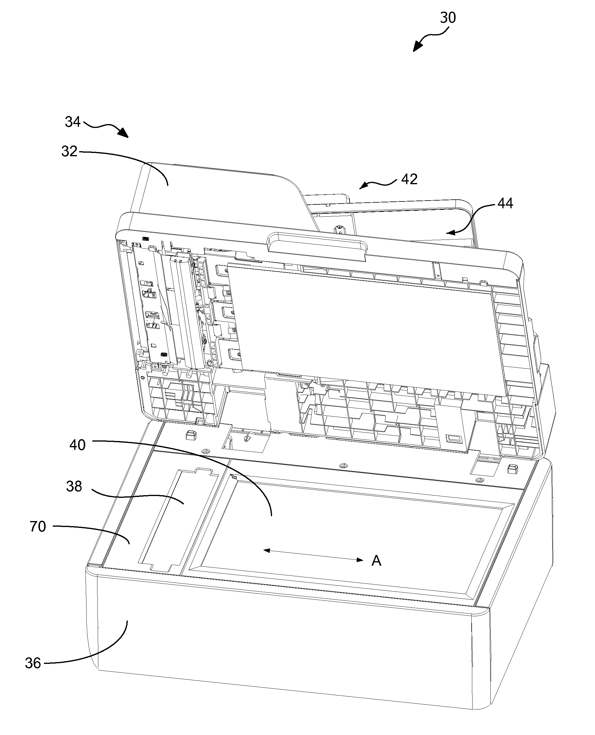
[0009]Exemplary embodiments of the present invention overcome the shortcomings of prior ADFs and thereby satisfy a significant need for an improved ADF having reduced occurrences of paper jams and motion shocks. According to an exemplary embodiment, an imaging apparatus includes an ADF having a media feeding section, a media collecting section and a media conveying path extending from the media feeding section to the media collecting section. The imaging apparatus includes a first scan head adjacent to the ADF. The first scan head is moveable to a raised position aligned with a first portion of the media conveying path for scanning a media sheet in the first portion of the media conveying path.

Problems solved by technology

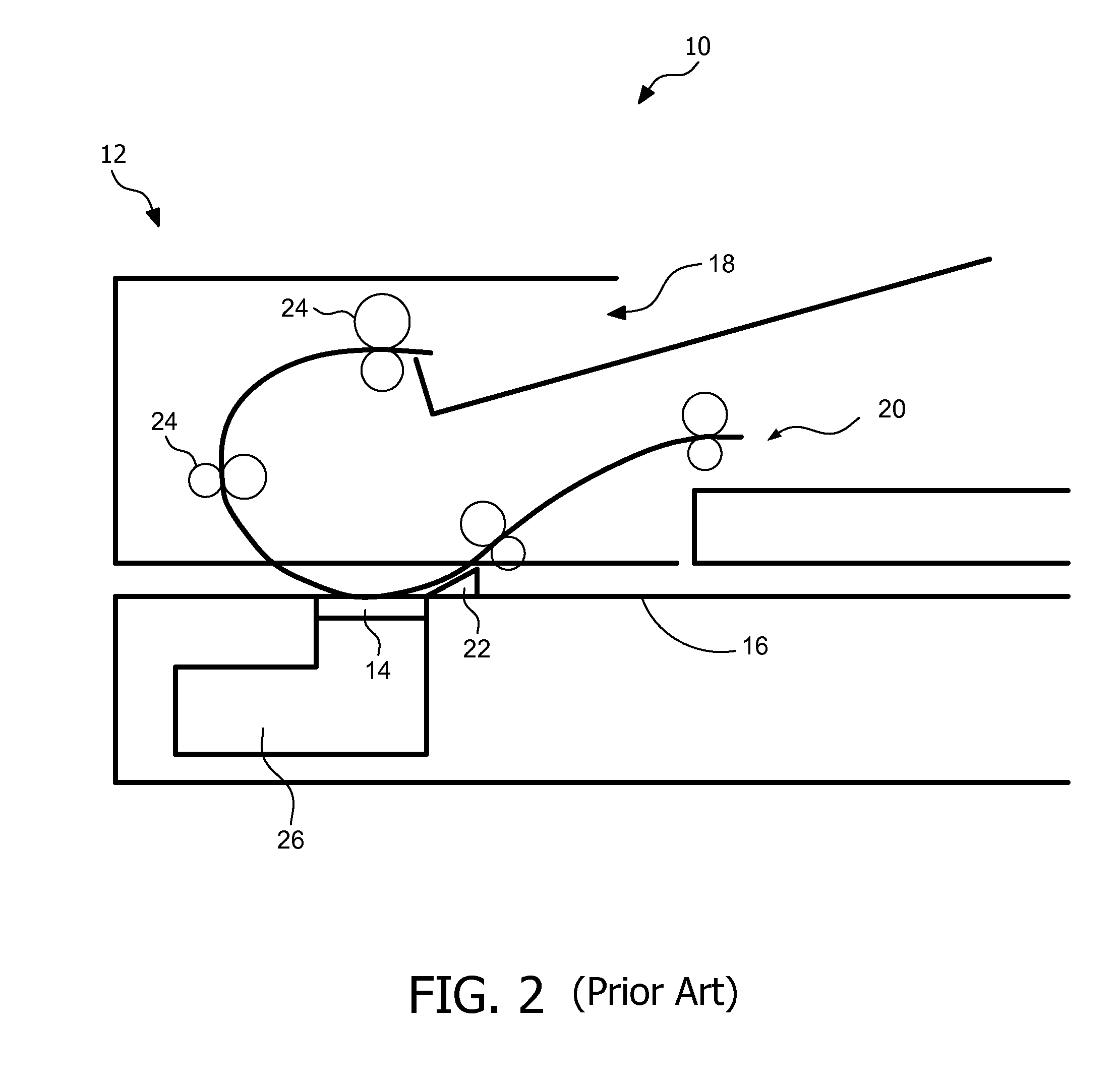
As shown in FIG. 3, a portions of the media conveying path adjacent to the imaging surface 14 are substantially circular, which has been seen to adversely affect the smooth transfer of media sheet to the media collecting section 20 and lead to paper jams and motion shocks in the media conveying path.

Method used


Image

  • Raisable Scan Head for an Imaging Apparatus
  • Raisable Scan Head for an Imaging Apparatus
  • Raisable Scan Head for an Imaging Apparatus

Examples


Embodiment Construction

[0026]It is to be understood that the invention is not limited in its application to the details of construction and the arrangement of components set forth in the following description or illustrated in the drawings. The invention is capable of other embodiments and of being practiced or of being carried out in various ways. Also, it is to be understood that the phraseology and terminology used herein is for the purpose of description and should not be regarded as limiting. The use of “including,”“comprising,” or “having” and variations thereof herein is meant to encompass the items listed thereafter and equivalents thereof as well as additional items. Unless limited otherwise, the terms “connected,”“coupled,” and “mounted,” and variations thereof herein are used broadly and encompass direct and indirect connections, couplings, and mountings. In addition, the terms “connected” and “coupled” and variations thereof are not restricted to physical or mechanical connections or couplings...


PUM


Abstract

An imaging apparatus includes an automatic document feeder having a media feeding section, a media collecting section and a media conveying path extending from the media feeding section to the media collecting section. The imaging apparatus includes a scan head adjacent to the automatic document feeder. The scan head is moveable to a raised position aligned with a portion of the media conveying path for scanning a media sheet in the portion of the media conveying path.

Description

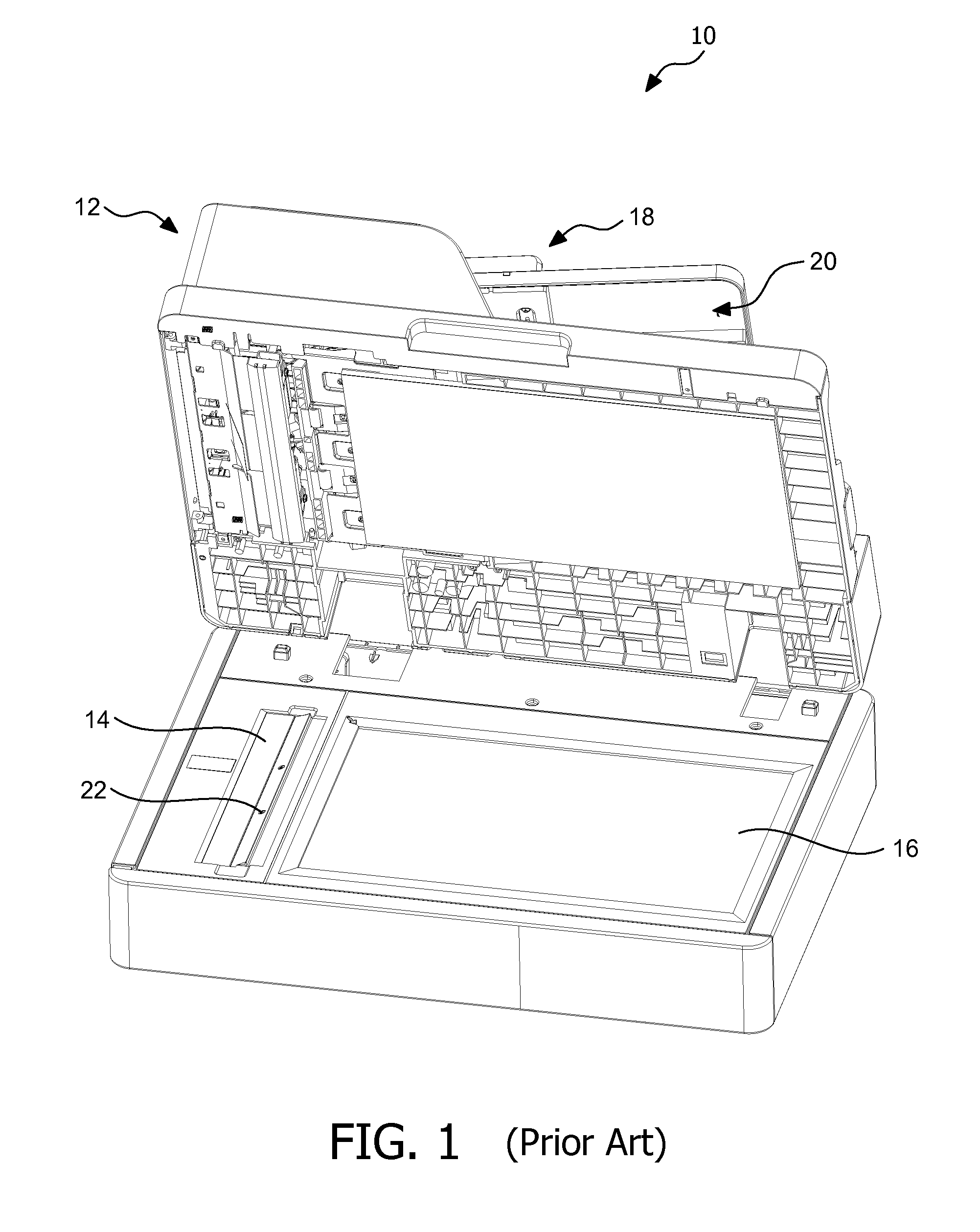
BACKGROUND[0001]1. Field of the Invention[0002]The present invention relates generally to an imaging apparatus and particularly to an imaging apparatus having a scan head that is raisable to a position for scanning a media sheet in the media conveying path of an automatic document feeder (ADF).[0003]2. Description of the Related Art[0004]An imaging apparatus, such as a copier, scanner, or a multi-function printing device (MFP) may include a scanning mechanism that operates in an ADF mode and / or a manual mode. A media sheet, such as paper or a transparency, when placed in an ADF or on a flatbed, is scanned by the imaging apparatus.[0005]FIG. 1 shows an existing imaging apparatus 10 that includes an ADF 12, an imaging surface 14 and an imaging surface 16. The imaging apparatus 10 works in two modes, ADF mode and manual mode. In manual mode, each media sheet is manually placed on the imaging surface 16 where the scanning operation takes place. Below the imaging surface 16, a scan head ...

Claims


Application Information

Patent Timeline
IPC IPC(8): H04N1/04
CPCH04N1/1017H04N1/121H04N1/123H04N2201/0446H04N2201/0081H04N2201/0442H04N1/193
Inventor CUI, CHENGWULANGREL, CHARLES BRANDON
Owner LEXMARK INT INC
Why Eureka
Eureka Blog
Learn More